E6. Passthrough AR: Spatial Awareness
Learning Outcomes
- Explain spatial awareness in passthrough AR. Describe how passthrough, head tracking, environmental understanding, and spatial registration allow virtual engineering content to appear within a physical workspace.
- Inspect the spatial-awareness systems already supplied by the Unity MR Template. Identify the tracked origin, camera, AR Foundation managers, permissions, object spawner, interactables, affordances, and spatial UI in the duplicated E6 working scene.
- Configure and evaluate
AR Plane Manager. Inspect detection mode, plane prefab, andARPlanetrackable behavior; visualize detected surfaces; and test sample object placement near detected surfaces.- Configure and evaluate
AR Mesh Manager. Verify provider support, assign a mesh prefab, tune density and vertex attributes, and observe environmental mesh generation where supported.- Configure and evaluate
AR Occlusion Manager. Request supported occlusion modes, confirm how depth information reaches rendering, and validate occlusion behavior with a sample object and physical occluder.- Distinguish planes, meshes, depth, bounding boxes, and anchors. Compare what each representation describes, what it can support, and why availability and quality vary across providers and devices.
- Validate provider support, permission, room setup, rendering, performance, registration, and physical safety. Test the complete experience on the standalone device and document unsupported-feature fallback behavior.
What Is Passthrough AR?
Passthrough AR presents a camera-mediated view of the physical environment inside a headset and composites Unity-rendered content into that view. Unlike optical see-through systems, the user does not look directly through transparent optics. External cameras capture the physical environment, and the headset displays that video together with virtual models, labels, controls, and effects. This camera-mediated design allows the system to combine a physical workspace with interactive virtual content, but it also introduces limitations. Passthrough images may contain distortion, latency, exposure changes, reduced resolution, imperfect depth cues, and a narrower effective field of view than normal vision. Therefore, passthrough AR content must be designed and tested with the same attention to scale, visibility, physical safety, and error recovery used in other engineering systems.
| Aspect | Mobile AR | Optical see-through AR | Passthrough AR |
|---|---|---|---|
| How the user sees the world | Live camera feed on a handheld screen | Direct view through transparent optics with projected graphics | Camera-mediated video inside a headset with composited virtual content |
| Typical interaction | Touch, device motion, screen-space controls | Hands, gaze, and voice on supported optical headsets | Controllers, hands, ray, poke, grab, and world-space UI through XRI |
| Strengths | Low cost, broad reach, portable deployment | Hands-free use with unobstructed direct environmental view | Reuses VR/XRI workflows; supports immersive headset tasks with the physical workspace visible |
| Limitations | Screen-held, smaller field of view, one-hand use | Brightness, field of view, and supply-chain constraints on some platforms | Mediated vision, latency, depth mismatch, and safety awareness requirements |
| Course role in Module E | Mobile AR tutorials (E2–E5) | Comparison and context only | Headset passthrough AR sessions in E6–E7 |
Unity uses the term Mixed Reality in the name of its official project template. In the remainder of this course, the general headset workflow is called passthrough AR.
Engineering Use Cases
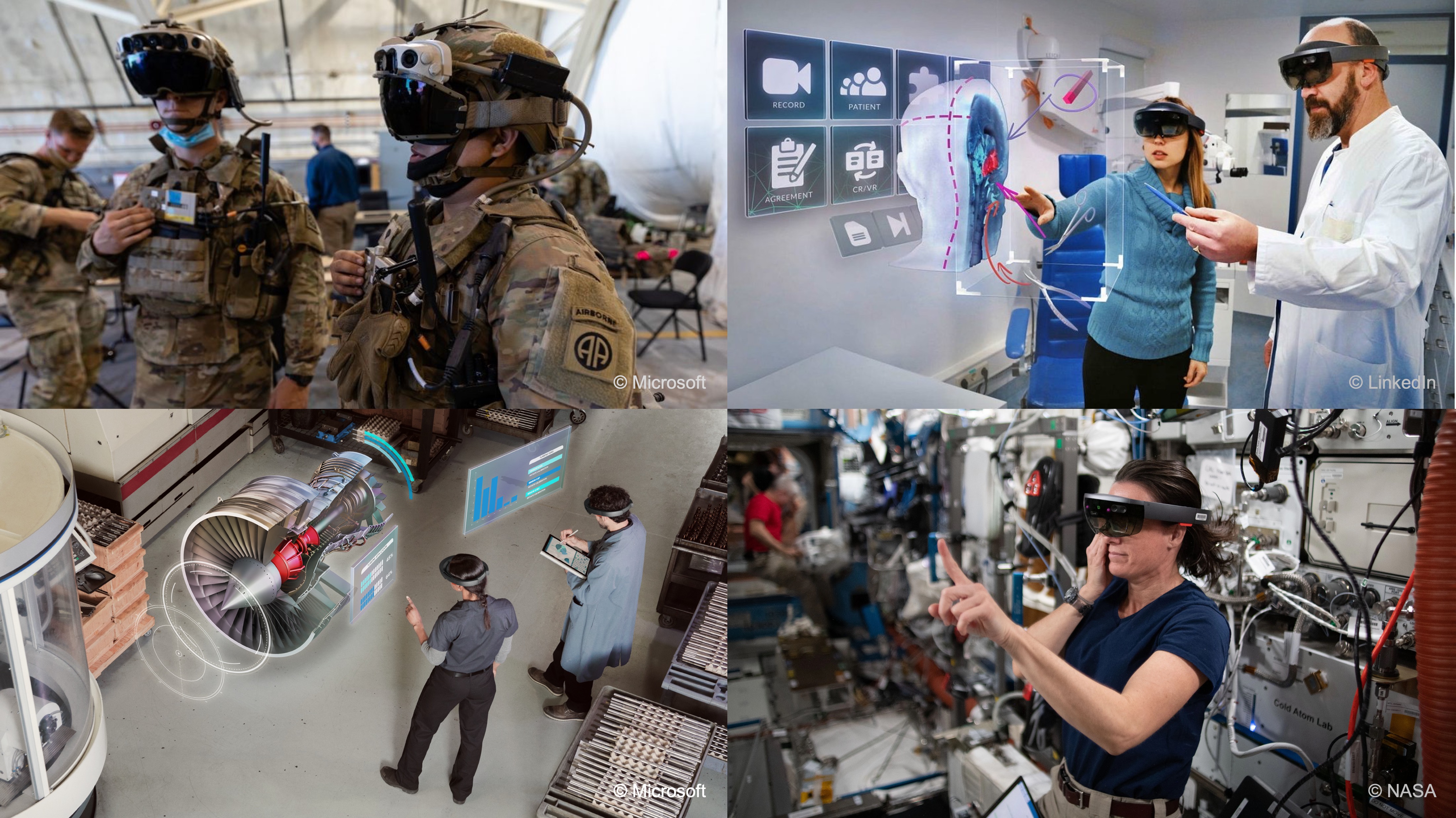
Passthrough AR is especially useful when virtual engineering information must be understood in relation to a physical location, surface, tool, or workstation. Its usefulness depends on accurate-enough scale, stable registration, readable feedback, and appropriate interaction—not simply on displaying a 3D model over a camera image. Prepared course assets such as Engine V8 and Drone Assembly illustrate these workflows; the same spatial-awareness principles apply to other engineering models.
- Assembly Visualization: Place an animated engine or assembly on a physical table so students can inspect structure, motion, materials, and component relationships from different viewpoints.
- Guided Assembly and Maintenance: Display task steps, labels, arrows, warnings, and part highlights near a real workstation. The overlays should support the task without hiding tools or hazards.
- Design Review and Prototyping: Preview the size, orientation, and access requirements of equipment before constructing or purchasing a physical prototype.
- Layout and Clearance Review: Visualize a machine footprint, operator zone, service envelope, or material-flow path within an existing facility.
- Training and Demonstration: Combine the user’s real surroundings with animated machines, process explanations, and status panels while maintaining awareness of the classroom or laboratory.
- Inspection and Diagnostics: Associate virtual indicators with physical locations to communicate operating states, possible faults, or inspection steps.
- Remote and Collaborative Review: Share spatially organized models and annotations with stakeholders. Shared coordinate alignment and persistent multiuser content require additional implementation beyond this session.
Safety note: Passthrough AR is not equivalent to unobstructed natural vision. Keep the physical workspace clear, use the headset’s boundary and physical-space setup, avoid stairs and moving machinery, and never treat a virtual overlay as safety-certified guidance.
Unity MR Template
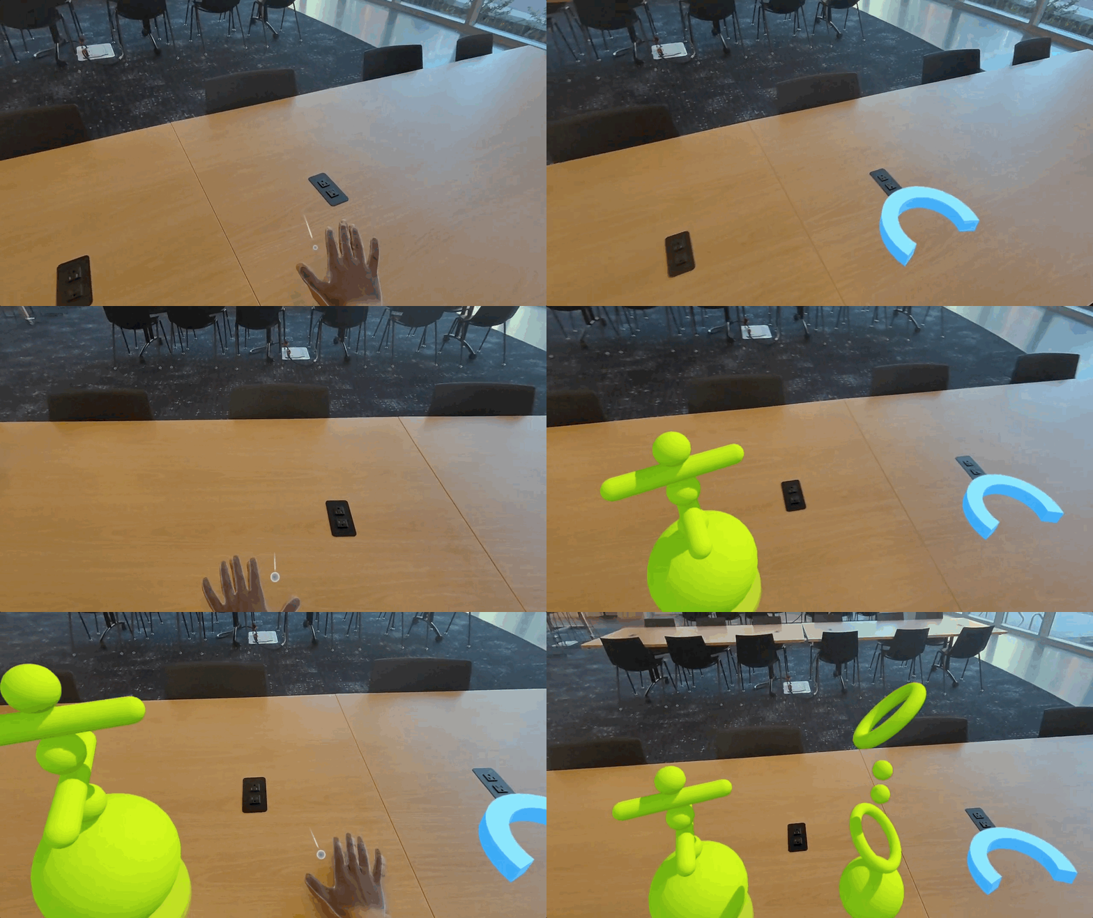
Unity’s Mixed Reality (MR) Template provides a preconfigured project and a SampleScene that demonstrate how OpenXR, AR Foundation, and the XR Interaction Toolkit work together. In this course, the template is an instructional starting environment: students inspect the supplied systems once, then use them to learn spatial-awareness concepts in passthrough AR. The template supports multiple Unity XR providers. The exact features available at runtime still depend on the active provider, device, permissions, and project configuration. A manager component in the hierarchy does not guarantee that the underlying platform supports every requested capability.
Create an MR Template Project
Begin with a known-working scene before changing provider settings or spatial-awareness configuration. This makes it easier to separate template, package, and application errors.
- Create the project:
- Open Unity Hub and create a project using the Mixed Reality template.
- Name the project
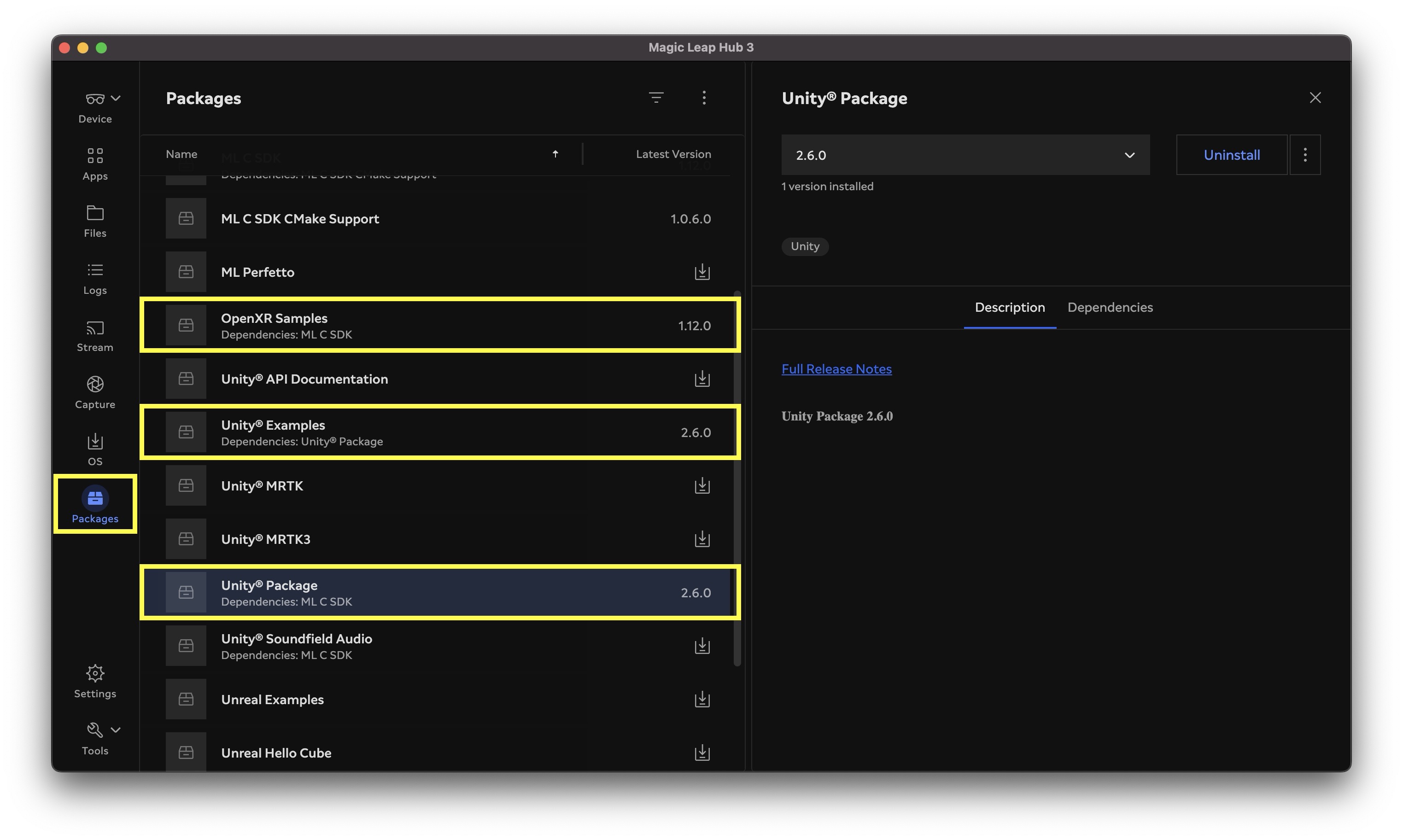
XFactoryPassthroughARor use the instructor’s required project name. - Use the course-supported Unity version.
- Allow the project to initialize:
- Wait for packages to import and scripts to compile.
- Resolve blocking Console errors before modifying spatial-awareness settings.
- Do not add another XR rig, input framework, or passthrough package.
- Select the deployment target:
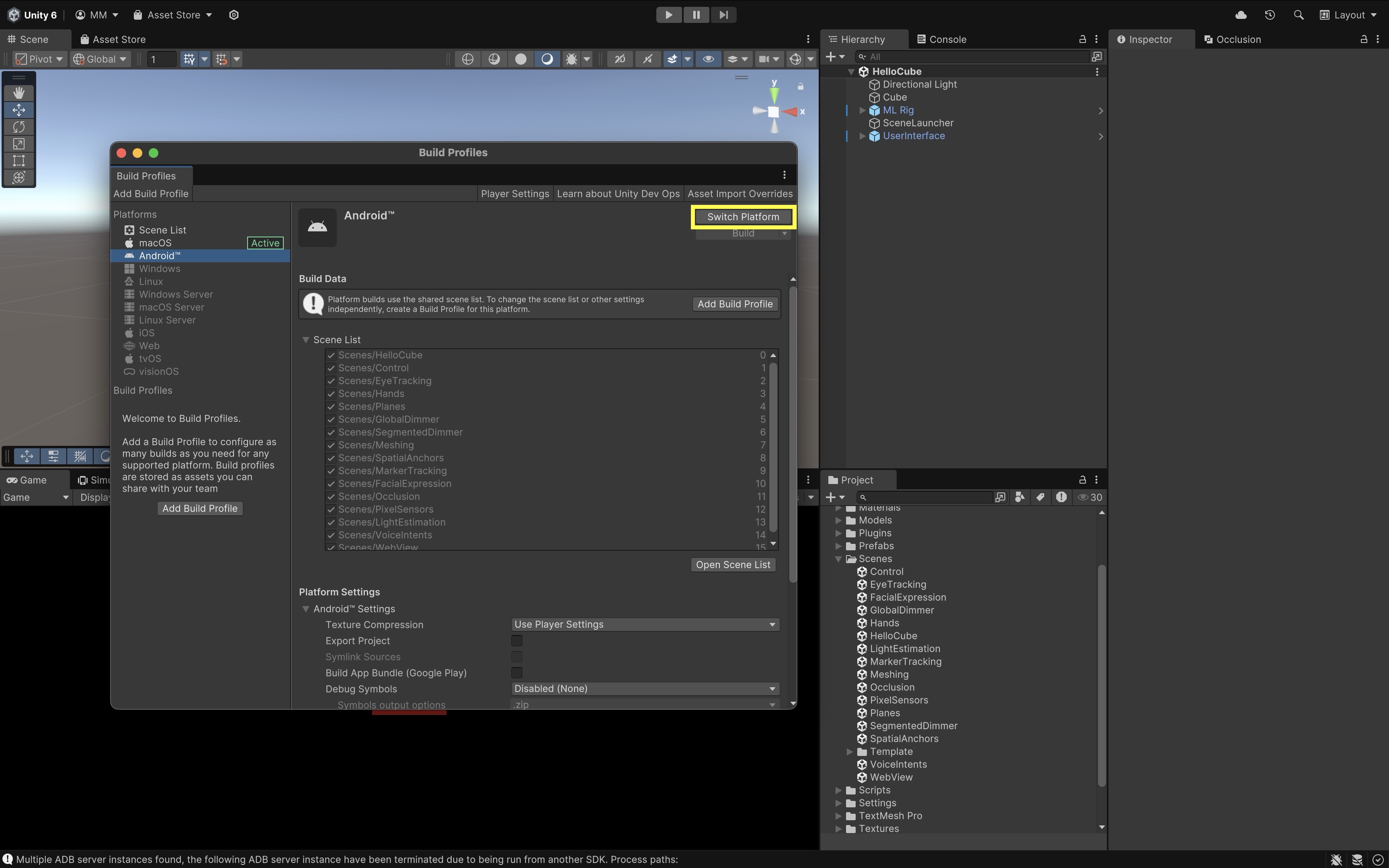
- Open
File > Build Profiles. - Select the course headset’s standalone Android/OpenXR target.
- Switch the active platform if needed.
- Open
- Review project validation:
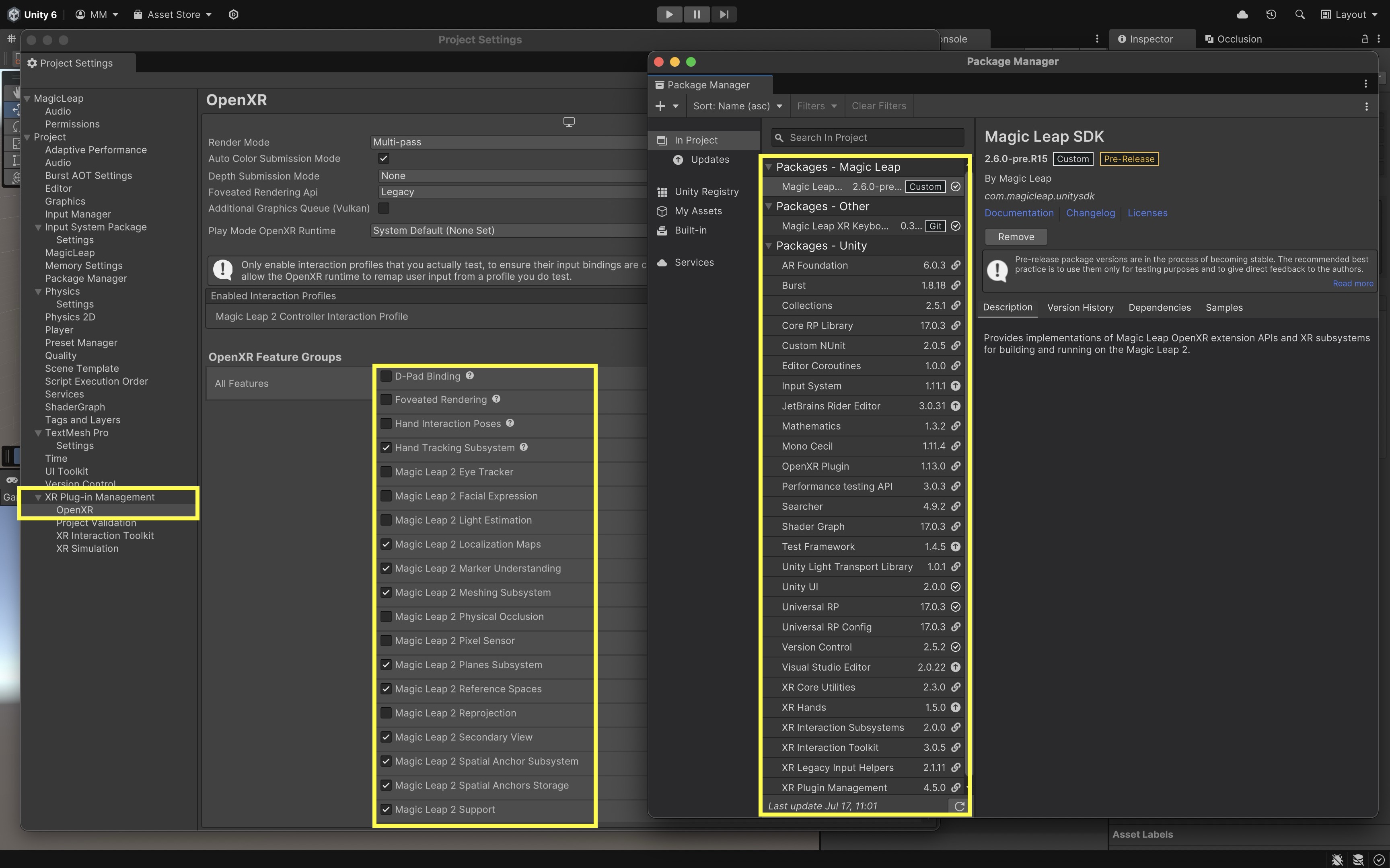
- Open
Edit > Project Settings > XR Plug-in Management > OpenXR. - Confirm that the intended provider feature group and controller profile are enabled.
- Run Project Validation and resolve relevant errors.
- Keep the template’s graphics and OpenXR presets unless the tutorial explicitly changes them.
- Open
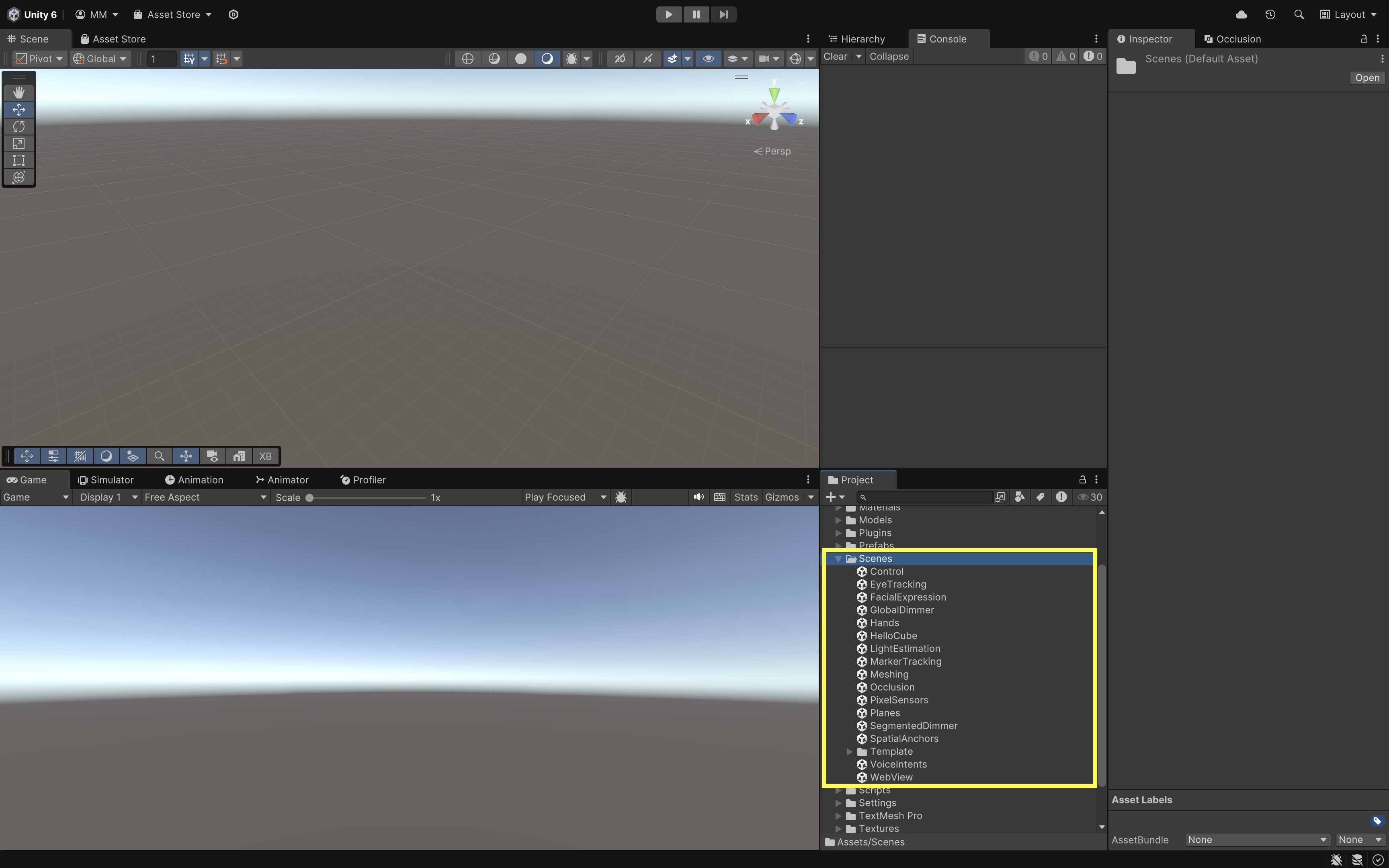
- Open the sample scene:
- Open
Assets/Scenes/SampleScene. - Run or deploy the unmodified scene once.
- Confirm that passthrough, input, and at least one sample interaction work.
- Open
- Create the E6 working scene:
- Stop Play Mode.
- Use
File > Save As. - Save the copy as
Assets/Scenes/E6_SpatialAwareness.unity. - Keep the original
SampleSceneunchanged as a reference.
The template documentation allows
SampleSceneto be used either as a reference or as the starting point after its demonstration content is removed. This course uses the second approach while preserving the original scene for comparison.
Scene Objects and Components
Expand the scene hierarchy and inspect the following systems before modifying them. Object names can vary slightly between template patch versions; use the installed project and Inspector as the final reference.
-
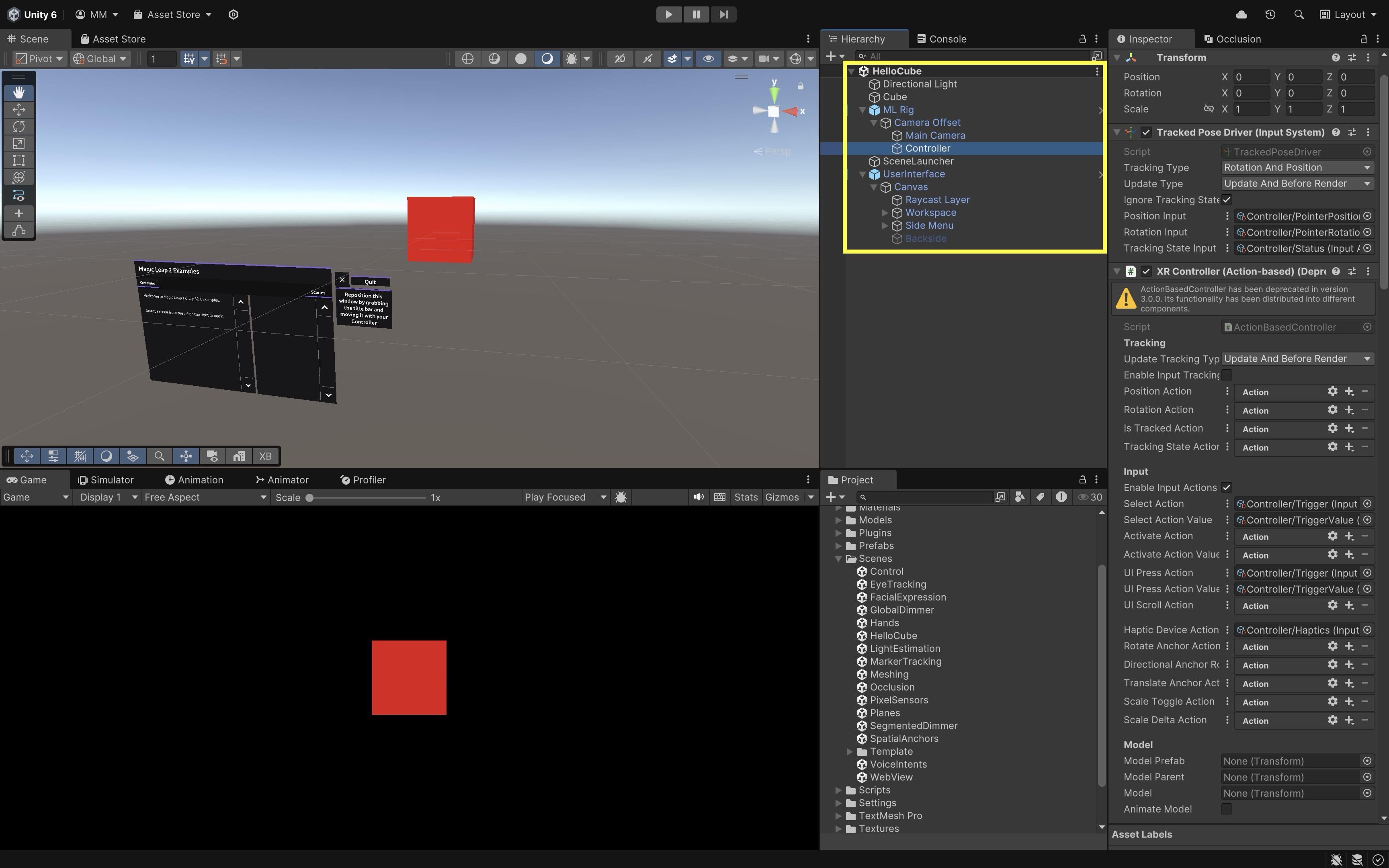
MR Interaction Setupis the primary configuration object for the tracked origin, camera, input systems, AR Foundation managers, permissions, object spawning, and supporting logic. It extends a basicXR Originwith systems needed for passthrough AR.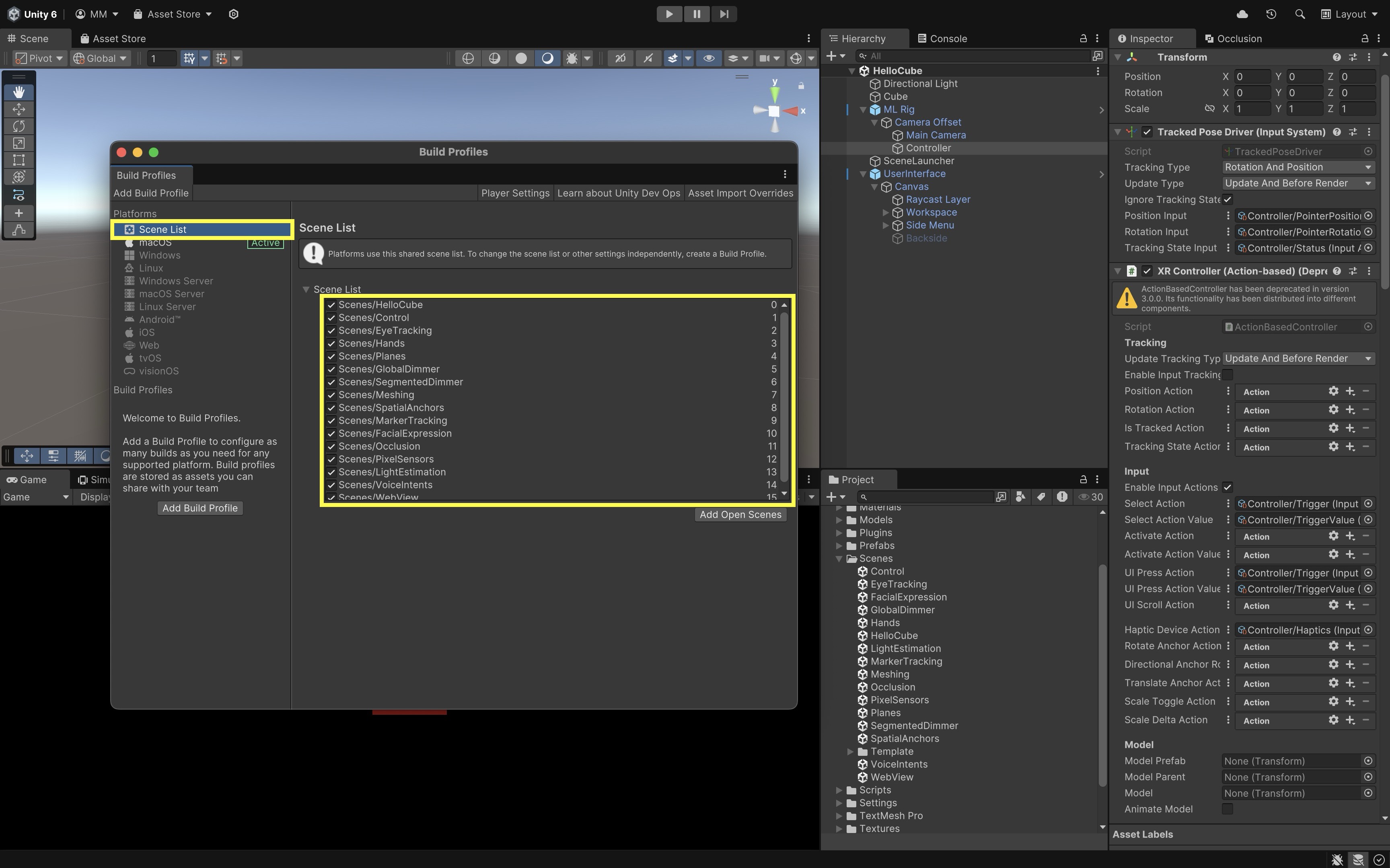
XR Origin: Defines the tracked coordinate origin and contains the camera and input hierarchy. Expand it in the Inspector to review key components commonly attached to or nested under the origin, including:Character Controller: Provides capsule-based collision constraints for grounded XR movement where the template uses continuous locomotion.Input Action Manager: Loads and enables the project’s Input System action assets used by XRI interactors.XR Input Modality Manager: Switches input handling between controller and hand-tracking modes when both are available.AR Plane Manager: Creates and tracks detected planes; discussed further in Plane Detection below.AR Bounding Box Manager: Exposes approximate 3D bounds and classifications where supported; discussed further in E7 Passthrough AR: Tracking & Anchors.Hand Subsystem Manager: Connects OpenXR hand-tracking data to the template’s hand input and interaction setup.AR Feature Controller: Coordinates which AR Foundation scene-understanding features are active in the template, such as planes, mesh, and occlusion.AR Anchor Manager: Creates and tracks spatial anchors where supported; discussed further in E7 Passthrough AR: Tracking & Anchors.AR Occlusion Manager: Requests environment-depth or geometry-based occlusion where supported; discussed further in Occlusion below.
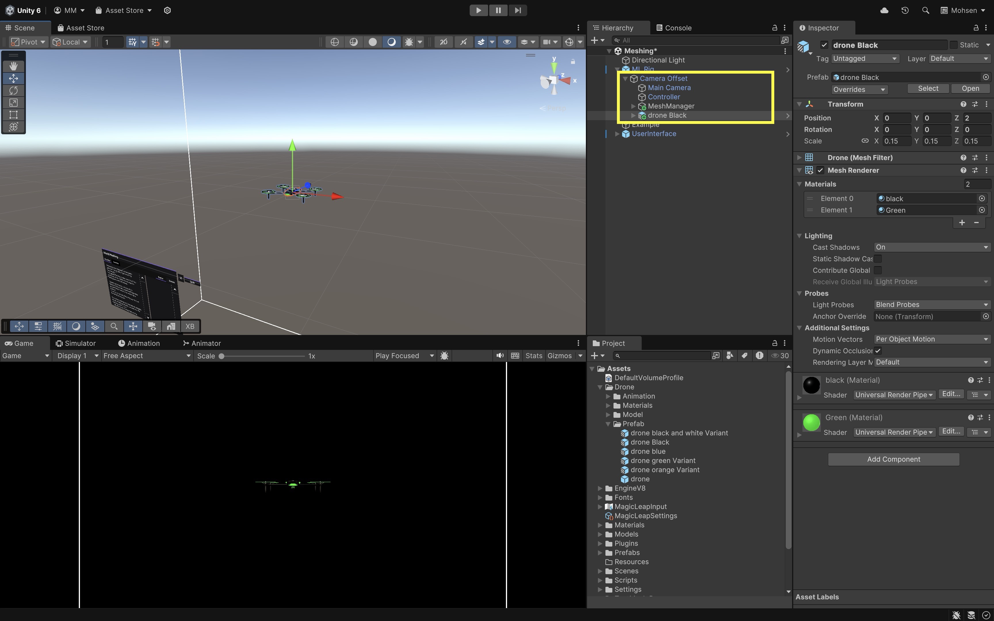
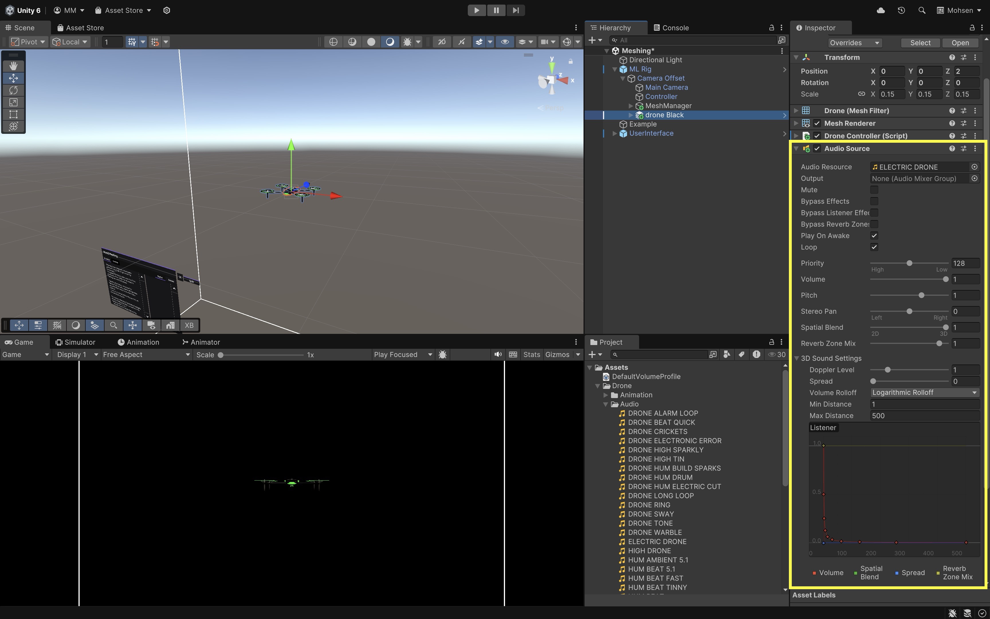
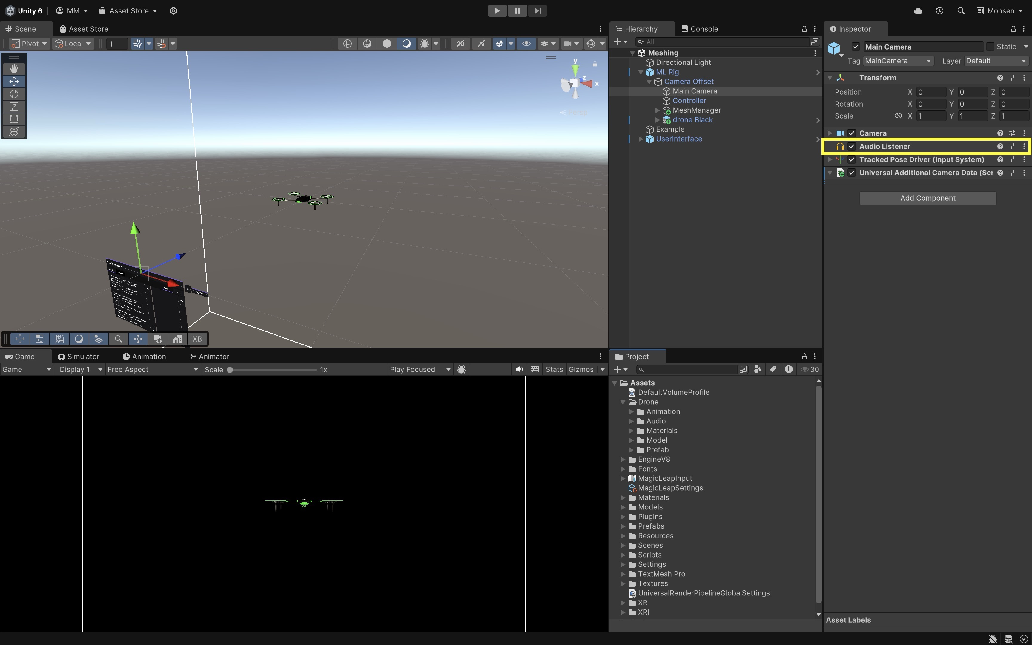
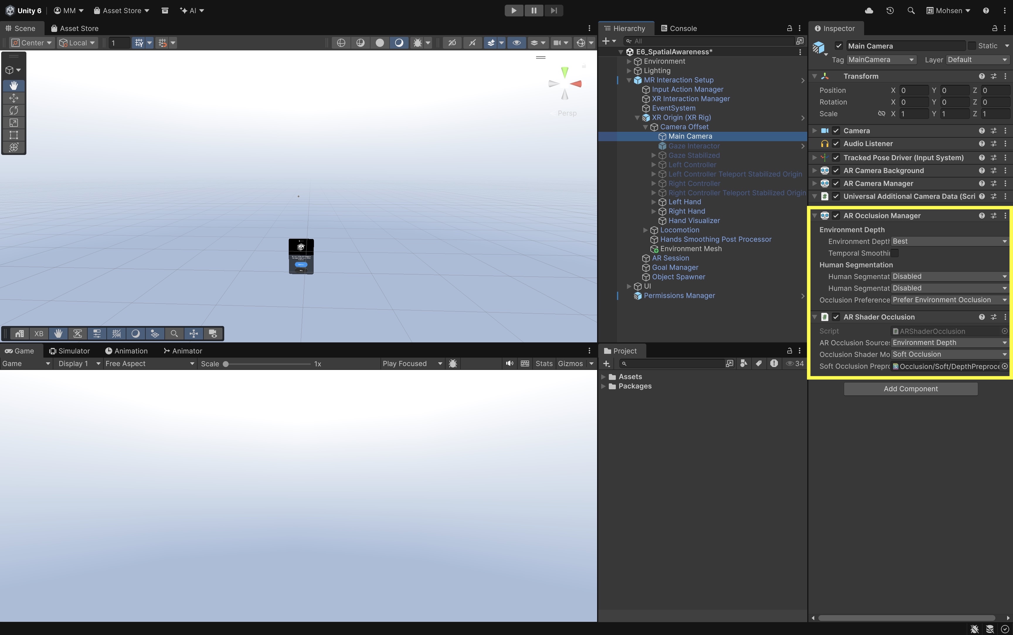
Main Camera: Renders the Unity scene from the user’s tracked viewpoint. Expand it in the Inspector to review key camera-related components, including:Camera: Defines the user’s view frustum, clipping, and rendering settings for the passthrough scene.Audio Listener: Receives spatial audio so 3D sound appears to originate from positions in the scene.Tracked Pose Driver: Applies the headset’s tracked position and rotation to the camera transform each frame.AR Camera Background: Configures how provider camera video is composited behind Unity content for passthrough.AR Camera Manager: Enables provider camera functionality and passthrough when supported; the background is typically configured with zero alpha so the physical environment remains visible.AR Occlusion Manager: May appear on the camera but is often disabled by default in the template because an equivalent manager is already configured elsewhere in the hierarchy; enabling duplicate occlusion managers can request conflicting depth paths on the same camera.AR Shader Occlusion: Makes environment-depth textures and projection data available to compatible shaders on OpenXR head-mounted displays where supported; discussed further in Occlusion below.
Left Hand,Right Hand: Hand-tracking hierarchies that reuse the same XRI interaction patterns introduced in Module D and apply unchanged in passthrough AR. Expand each hand in the Inspector to review key components, including:Poke Interactor: Supports close-range poke and near-touch UI interaction.Near Far Interactor: Combines near direct interaction and far ray interaction from the same tracked hand.Aim Pose: Provides the tracked transform used as the origin for hand-based aiming and raycasts.Punch Grab Pose: Provides the direct-interaction attachment point used for grab and manipulation.Pinch Point Stabilized: Supplies a stabilized pinch location to reduce jitter during precise selection.Palm: Hosts palm-attached behaviors such as theContact Spawn Triggerused for spawning and hand-menu gestures.
AR Session: Controls the lifecycle of the AR session. The scene should contain only one active session.-
Goal Manager: Drives the template Coaching UI through a queued onboarding flow—welcome, find surfaces, tap to spawn—and advances steps by coordinating withAR Feature Controller,Object Spawner, the lazy-follow goal panel, tap tooltip, and learn modal.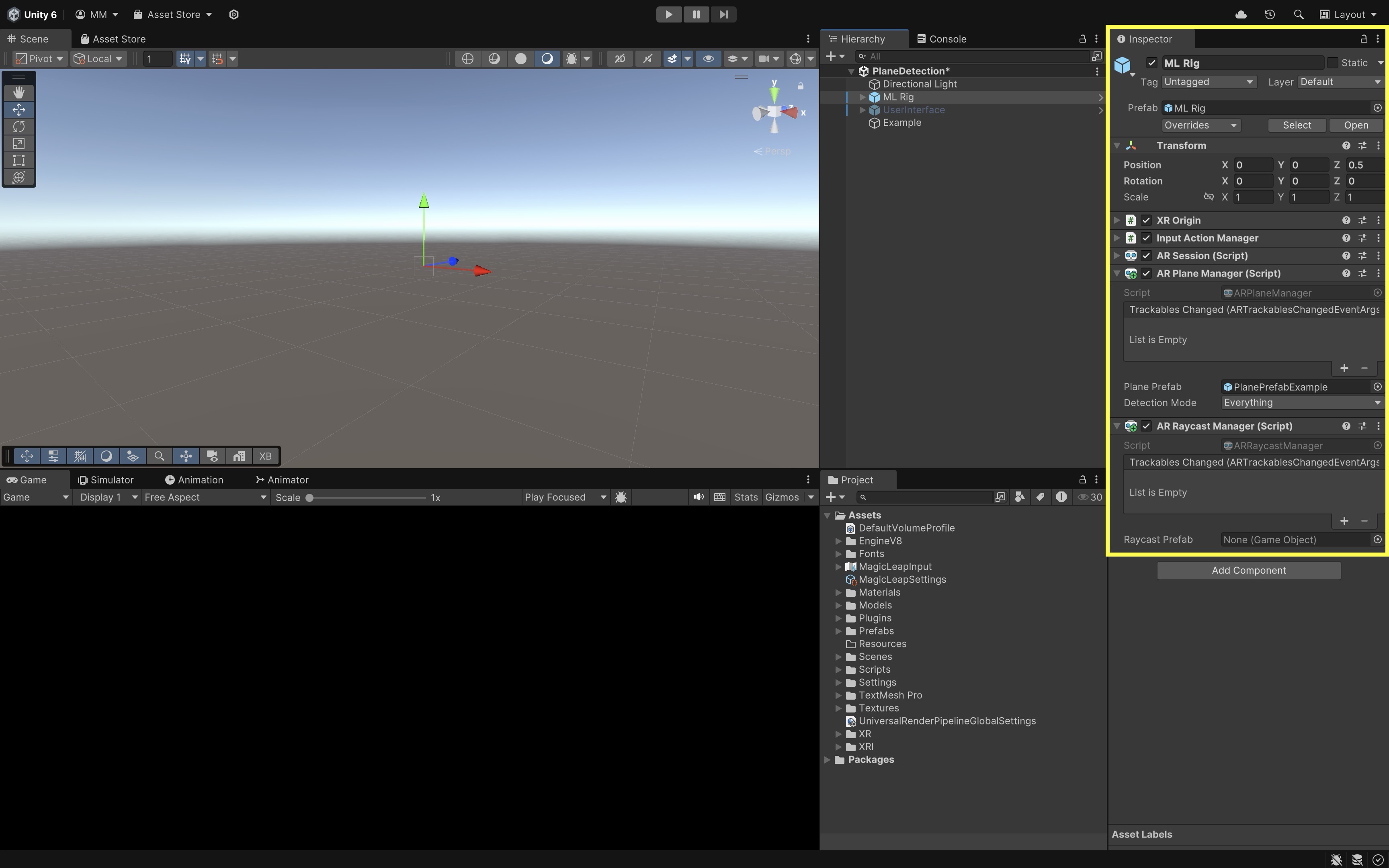
Object Spawner: Holds a list of prefabs that can be created through the sample’s spawning interaction (covered next).-
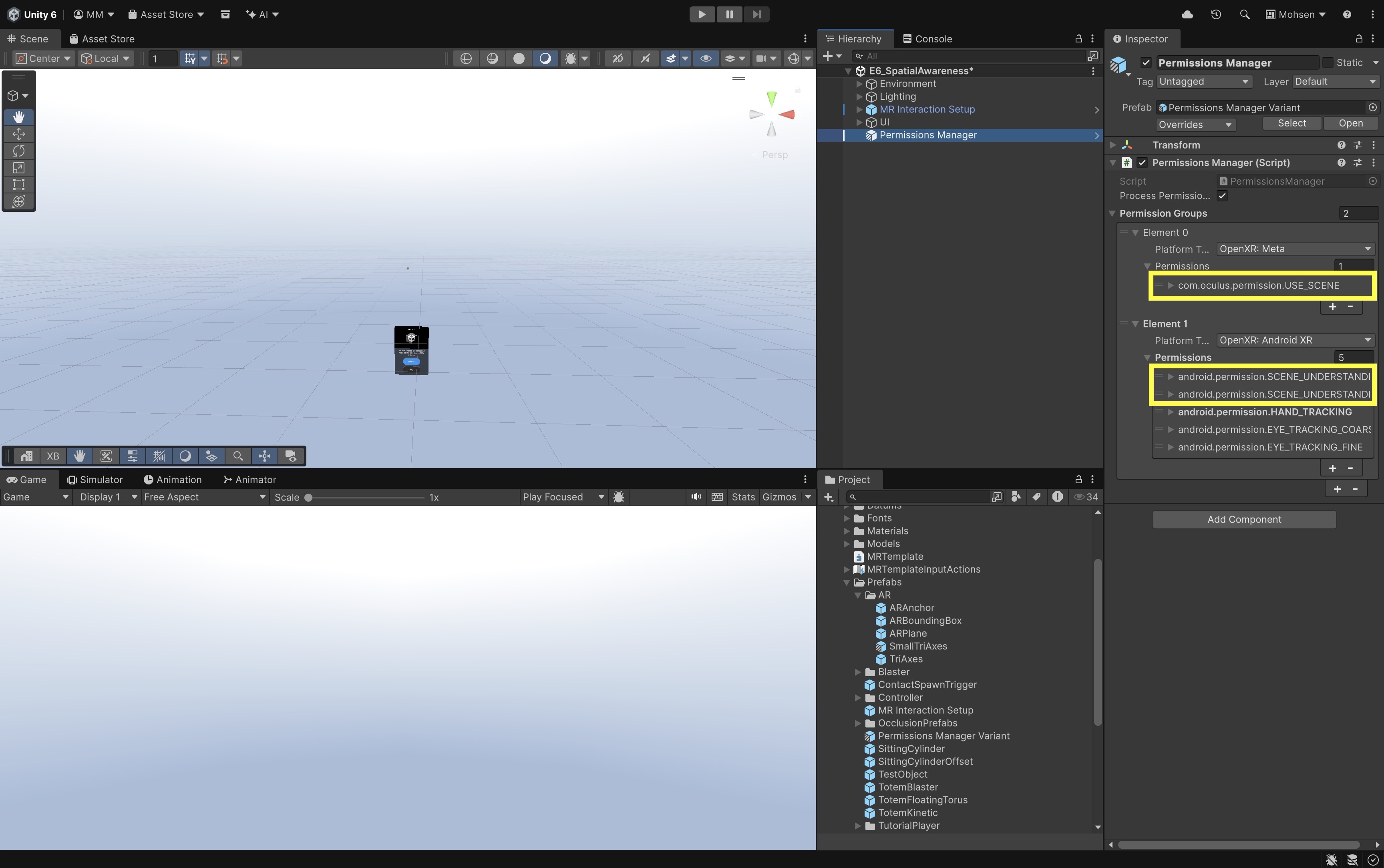
PermissionsManager: Requests and responds to permissions for features such as hand tracking and scene understanding. On providers that require scene-data permission, keepAR Plane Manager,AR Bounding Box Manager,AR Mesh Manager, andAR Occlusion Managerdisabled until permission is granted. After permission succeeds, enable only the managers needed for the current activity. If permission is denied, leave those managers disabled and use the documented fallback. An enabled manager in the hierarchy does not by itself produce runtime scene data.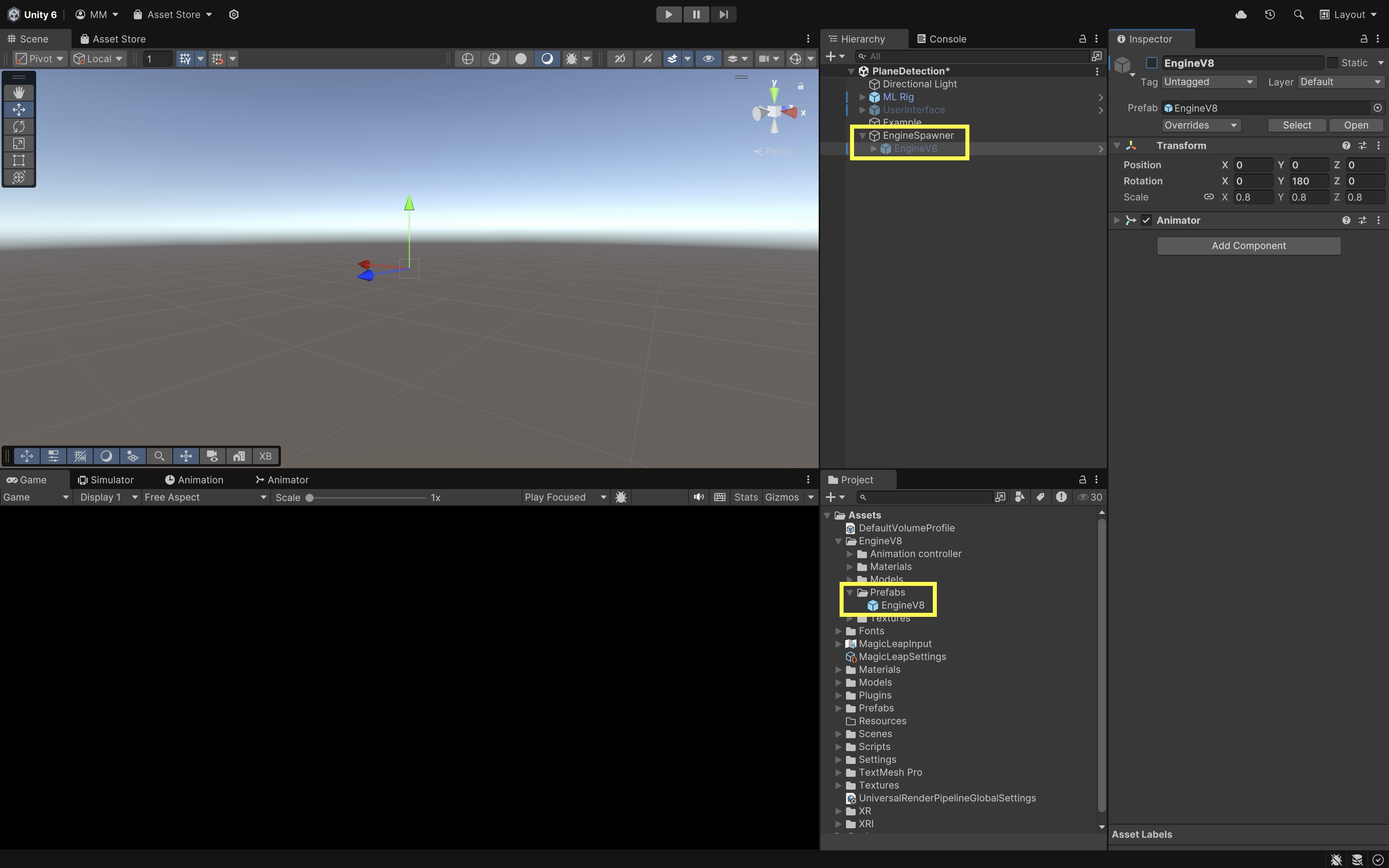
Do not copy only the XR Origin into a new scene. The working example also depends on the AR session, managers, permissions, interaction manager, input actions, spawner, UI, and related event systems.
Sample Systems
The template includes several sample systems that connect spatial awareness, object interaction, feedback, and user controls. These systems serve two purposes in this session: they demonstrate how the template’s AR Foundation and XRI components work together, and they provide reusable starting points that can be simplified for engineering applications such as plane review, bounding-box inspection, occlusion testing, anchor operations, and object spawning.
Object Spawner
The Object Spawner stores an Object Prefabs collection and determines which sample or engineering prefab the template creates at runtime. The selected prefab can be changed through the hand menu or other sample UI connected to the spawner. Spawning is initiated by the palm-mounted Contact Spawn Trigger. Depending on the prefab, spawned objects may already include interactable components, affordance receivers, XRI grab transformers, or anchor-related behavior. The Object Spawner is especially useful for testing several engineering assets without writing separate spawn logic for each one.
- Locate the Object Spawner under
MR Interaction Setup. -
Locate the
Spawned Objects Manager, which coordinates the template’s spawned-object workflow by tracking spawned prefabs, attaching them to anchors, connecting object-selection and deletion controls, and saving, loading, or erasing persistent anchors where supported.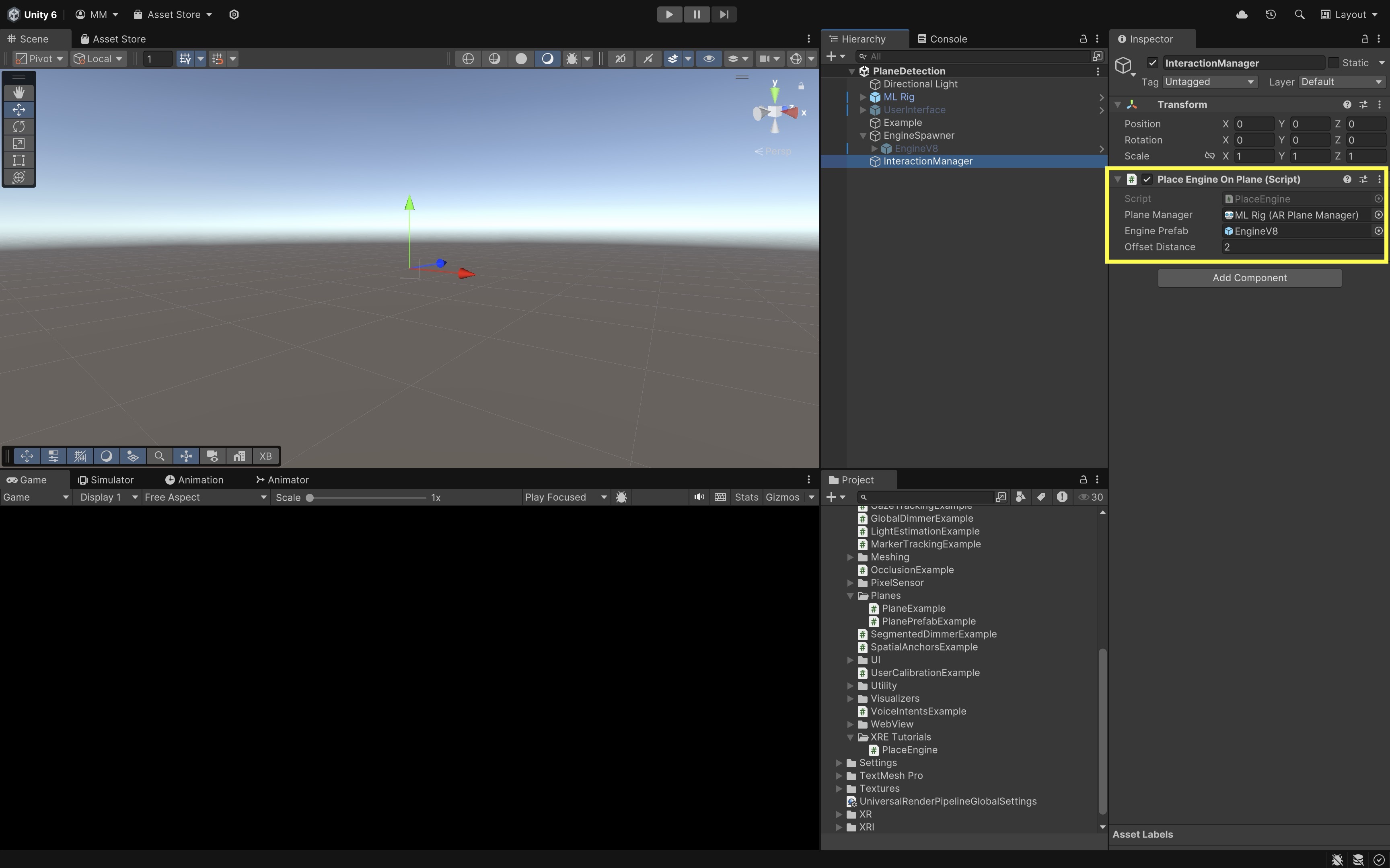
- Inspect the
Object Prefabslist. -
Identify which prefab is currently selected by default.
-
Locate the palm-mounted
Contact Spawn Triggeron the hand hierarchy, which uses the template’s existing collision-based spawn workflow rather than a custom placement script.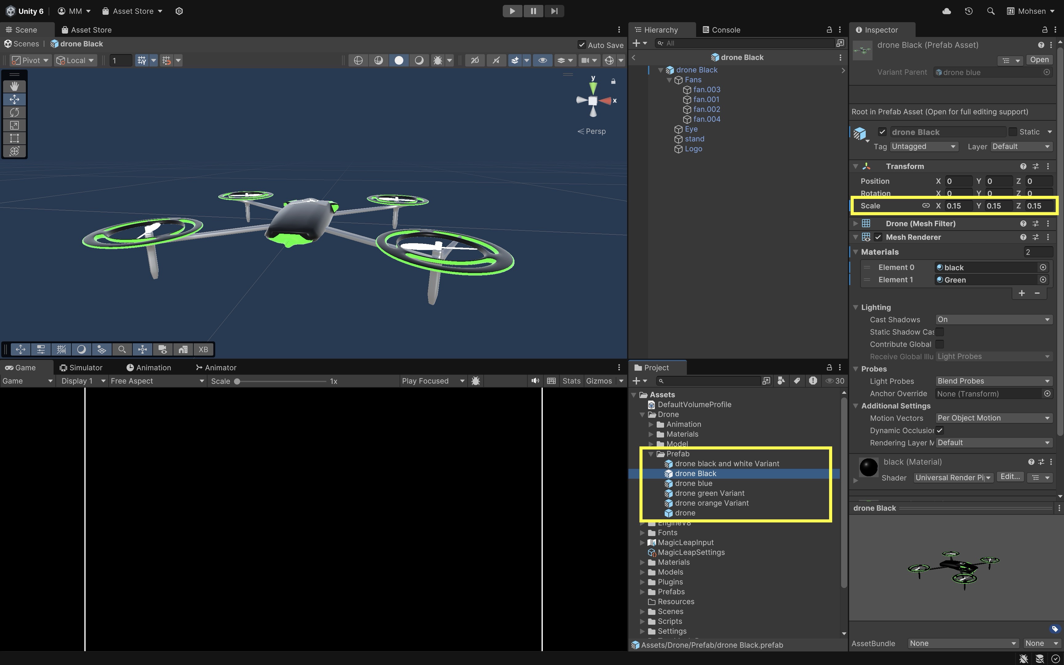
-
Build and run the scene. Spawn one existing sample object through the installed template workflow. Change the selected prefab through the sample UI and spawn another object.
Interactables and Affordances
The sample includes four interactable prefabs in the Object Spawner list:
- Sitting Cylinder Offset: A basic physics-based grab interactable that uses XRI grab components and can collide with represented physical geometry. Its hover and select affordances communicate interaction state.
- Totem Floating Torus: A grab-interactable base that demonstrates movement through standard XRI grab components, with a separate floating interactable above it. The base setup can be preserved while replacing the visual content with an engineering model.
- Totem Blaster: A grab-interactable base using the same XRI movement pattern, paired with an upper object that demonstrates particle-based activation. Affordances provide feedback for hover, selection, and activation.
- Totem Kinetic: A grab-interactable base with a separate upper object that demonstrates passive hand-physics interaction. Students can retain the base interaction and affordance setup while substituting their own visual or engineering content.
Their upper objects demonstrate separate interaction patterns, including floating-object manipulation, passive hand-physics interaction, and particle activation. Inspect and test the installed prefabs to determine whether their base movement is additionally constrained by detected planes or whether it follows standard XRI grab behavior.
Grabbing and movement on the three totem prefabs are enabled through the template’s standard XRI grab setup on each base object. The root XR Grab Interactable receives direct or ray selection, while the paired XR General Grab Transformer calculates how the object moves during the grab.
XR Grab Interactable: Defines the grabbable base, collider references, attach behavior, and movement settings used when the user selects the totem root.XR General Grab Transformer: Applies the template’s default grab movement rules, including axis constraints configured on the totem base.
For engineering adaptation, preserve the base
Rigidbody, collider,XR Grab Interactable,XR General Grab Transformer, and affordance components, then replace only the visual or engineering content child.
Coaching UI
The Coaching UI introduces the user to the sample’s interaction workflow and presents onboarding instructions or goals without permanently occupying the user’s view. It is coordinated by the Goal Manager under MR Interaction Setup and can guide users through actions such as opening the hand menu, spawning an object, manipulating content, or exploring spatial features. The same pattern demonstrates how contextual instructions can appear when needed and then step aside.
- In the installed template, the coaching sequence typically progresses through goals such as welcome, find surfaces, and tap to spawn.
- As each step completes, the
Goal Managerenables or disables related UI objects, adjusts lazy-follow behavior on the goal panel, coordinates withAR Feature Controller, and listens for events such as object spawning before advancing. - Inspect the Coaching UI to understand:
- the Coaching UI hierarchy;
- the
Goal Managercomponent and its referenced UI objects; - the sequence of goals or instructional states;
- how a completed interaction such as spawning advances the coaching sequence;
- which instructions would remain useful in a simplified engineering application.
The same pattern can support engineering onboarding for setup guidance, workstation calibration, permission or room-setup instructions, placement confirmation, task-step introductions, or recovery messages when tracking is limited.
Hand Menu Setup MR Template Variant
Hand Menu Setup MR Template Variant is an especially useful prefab because it provides an existing hand-attached spatial control interface that students can simplify and reuse in their own passthrough AR projects. General behavior: the menu stays attached to the hand, opens when the configured palm-up activation pose is detected, and reuses the template’s existing XRI spatial UI for sample controls instead of requiring a new world-space Canvas. The MR Template variant organizes controls into tabs. In current template versions, the hand menu commonly includes groups such as:
- Assets: Object selection for the Object Spawner and a Delete All control for active spawned objects.
- Planes: Show, hide, or configure detected-plane visualization where supported.
- Bounding Boxes: Show, hide, or toggle bounding-box visuals and debug information where supported.
- Persistent Anchors: Save, load, or erase saved persistent anchor data where supported.
- Occlusion: Enable, disable, or configure supported occlusion behavior or visualization.
Some template versions also expose general sample or debug visualization settings through additional controls. A hand-menu button may appear even when the underlying manager is disabled, unsupported on the active provider, or waiting for permission and room setup.
To reuse a simplified version in an engineering project:
- Duplicate the prefab or create a prefab variant rather than modifying the package original.
- Remove sample tabs and controls that are irrelevant to the project.
- Keep only the controls required by the application, such as show/hide planes, show/hide bounding boxes, enable/disable occlusion, save anchor, load anchor, and clear active content.
- Reconnect retained controls to the project’s existing managers and public methods.
- Update labels so they describe the engineering application rather than the template demo.
- Preserve the existing XRI hand-menu activation and UI interaction configuration.
- Validate hand-menu readability, reachability, accidental activation, and physical-space awareness on the standalone device.
Do not copy every sample control into an engineering build. A simplified menu should expose only actions that are understandable, supported, and useful to the user.
Spatial Panel Manipulator
The Spatial Panel Manipulator is a movable world-space panel that can be grabbed by its header or handle and can use Lazy Follow behavior. It supports near and far interaction through the template’s existing XRI setup. It provides a larger workspace for instructions, status, data, or task controls that should remain visible in the environment. Possible engineering uses include task status, assembly steps, detected-feature status, tracking warnings, selected anchor information, placement acceptance or rejection, and machine or process information.
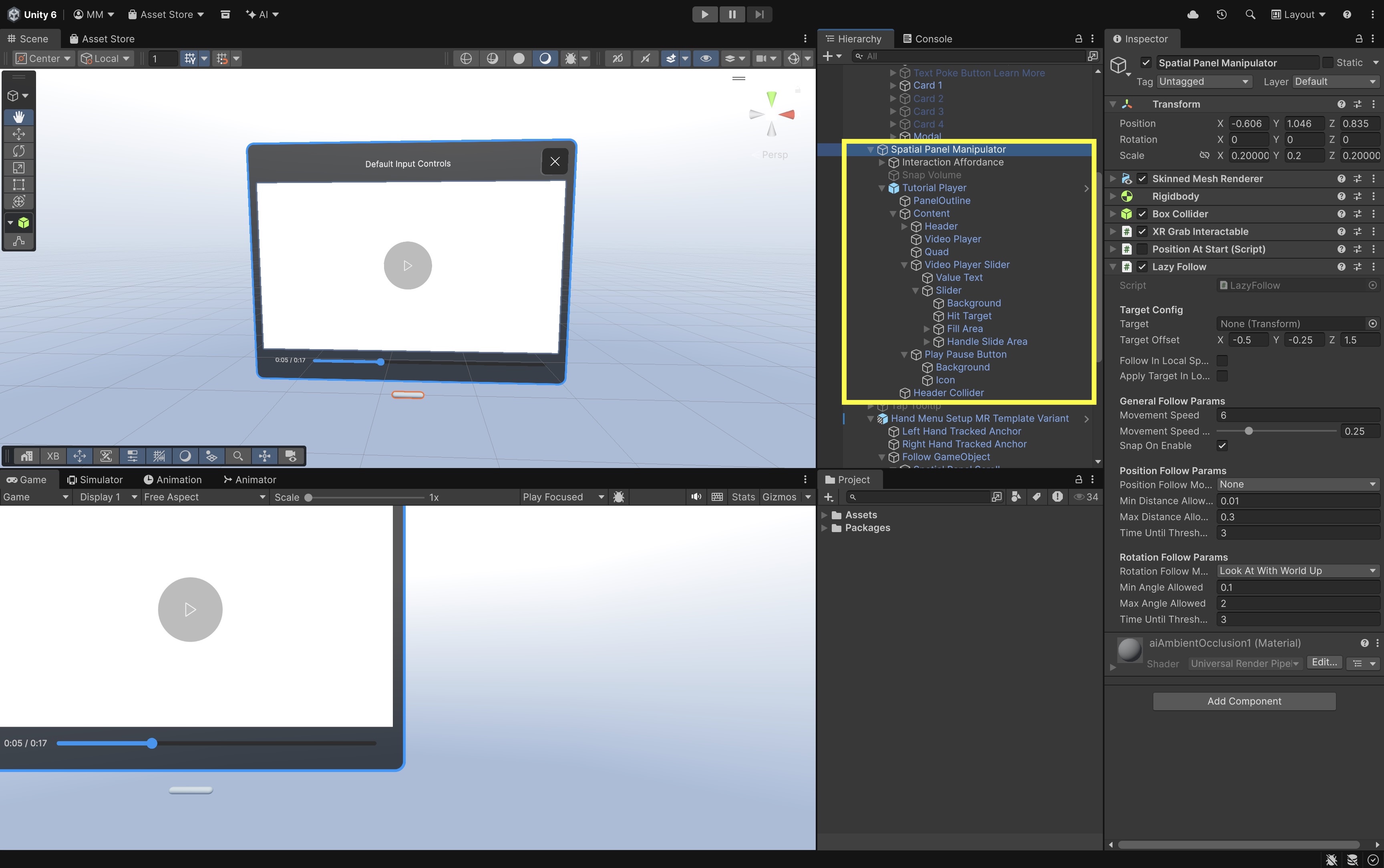
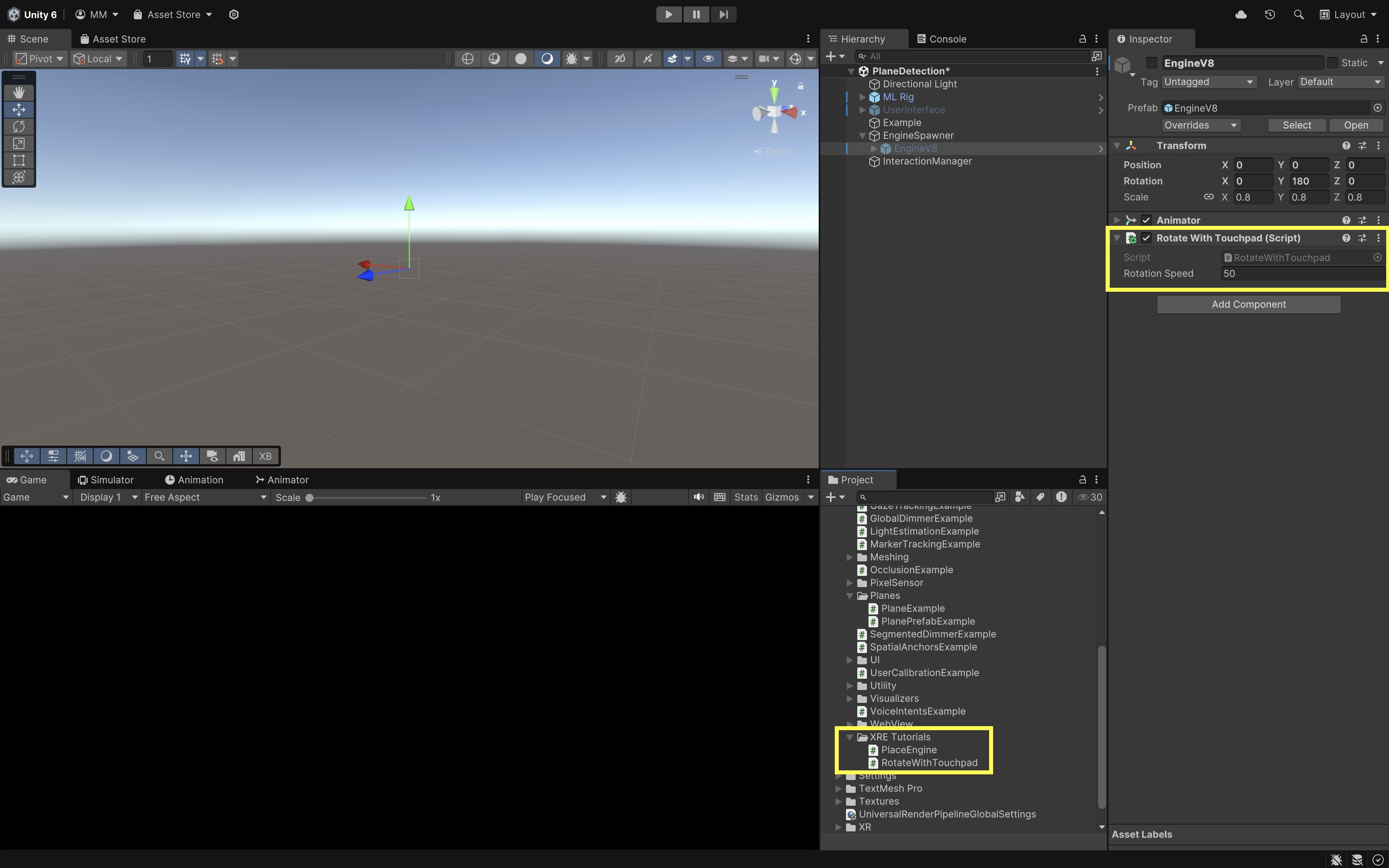
To apply the sample systems to your engineering project, you may add an already prepared Engine V8, Drone Assembly, or project-specific prefab to the Object Spawner while preserving the sample’s grab-interactable base and affordance components. You may also duplicate
Hand Menu Setup MR Template Variantand remove unnecessary tabs, retaining only controls such as plane visualization, bounding-box visualization, occlusion, anchor operations, and active-content reset. Calibrate the engineering model’s scale, pivot, and orientation, and verify that every retained menu control corresponds to a supported manager or application action.
What Is Spatial Awareness?
Spatial awareness is the system’s ability to relate virtual content to the user’s tracked pose and to available information about the physical environment. A spatially aware application does more than render an object in front of the camera: it uses information about position, orientation, surfaces, geometry, and depth to place and display content coherently as the user moves. These concepts build on the AR Foundation architecture introduced in E2 AR Foundation and the mobile spatial-awareness walkthrough in E3 Mobile AR: Spatial Awareness. After reviewing the Unity MR Template and the systems it provides, this section introduces the underlying spatial concepts that support placement, registration, rendering, and interaction within the physical workspace.
Spatial Awareness Capabilities
The major spatial-awareness capabilities used in this module are:
- Device Tracking: Estimates the headset’s position and orientation so the virtual camera moves with the user’s head.
- Passthrough: Presents the camera-mediated physical environment behind the Unity scene.
- Plane Detection: Represents sufficiently flat regions such as floors, tables, countertops, ceilings, or walls where supported.
- Raycasting: Tests where a ray intersects a detected plane, depth surface, mesh, bounding box, or Unity collider.
- Meshing: Represents physical geometry as connected triangles rather than only as flat planes.
- Occlusion: Uses depth or geometry so a physical object can visually hide virtual content that should appear behind it.
- Anchors: Maintain a tracked pose for virtual content after placement. Anchoring, persistence, and scene understanding are developed in E7 Passthrough AR: Tracking & Anchors and were first implemented on mobile in E5 Mobile AR: Anchors.
- Spatial Feedback: Uses world-space UI, visual affordances, and spatial audio to communicate where content is and how it can be used.
| Spatial feature | Representation | Typical engineering use | Main limitation |
|---|---|---|---|
| Plane | Flat pose, dimensions, and boundary | Tabletop placement, floor zones, wall panels | Simplifies curved and irregular geometry |
| Mesh | Triangle geometry | Clearance visualization, collision approximation, spatial debugging | Can be incomplete, coarse, or expensive |
| Depth | Per-pixel distance from the viewer | Dynamic occlusion and depth-aware rendering | Noisy near edges, thin objects, and reflective surfaces |
| Anchor | Tracked spatial pose | Stabilizing confirmed content | Does not describe surrounding geometry |
| Bounding box | Approximate 3D extent and classification | Finding a table, screen, storage unit, or other known object | Does not reproduce the object’s exact shape |
These representations are complementary. A detected table plane can provide a convenient placement surface, an environmental mesh can reveal surrounding geometry, depth can improve visual occlusion, and an anchor can stabilize the final content pose. No single feature provides a complete understanding of the physical environment.
Registration & Drift
-
Spatial Registration: Registration describes how accurately virtual content aligns with its intended location in the physical environment. A model is well registered when it appears at the correct position and orientation and maintains that relationship as the user changes viewpoint. Registration is essential in engineering applications because even small alignment errors can make an assembly guide, clearance visualization, or equipment overlay misleading.
-
Drift: Virtual content may appear misregistered from the start because of an inaccurate placement pose, an unsuitable model pivot or orientation, or limitations in the environmental representation. Registration may also degrade over time through drift, where the apparent relationship between virtual and physical content changes as tracking uncertainty accumulates or the system relocalizes.
In E6, evaluate registration visually by walking around a placed sample object or engineering model and checking whether it remains aligned with the selected surface. E7 introduces anchors, tracking-state feedback, and recovery behavior to improve and evaluate spatial stability.
Plane Detection
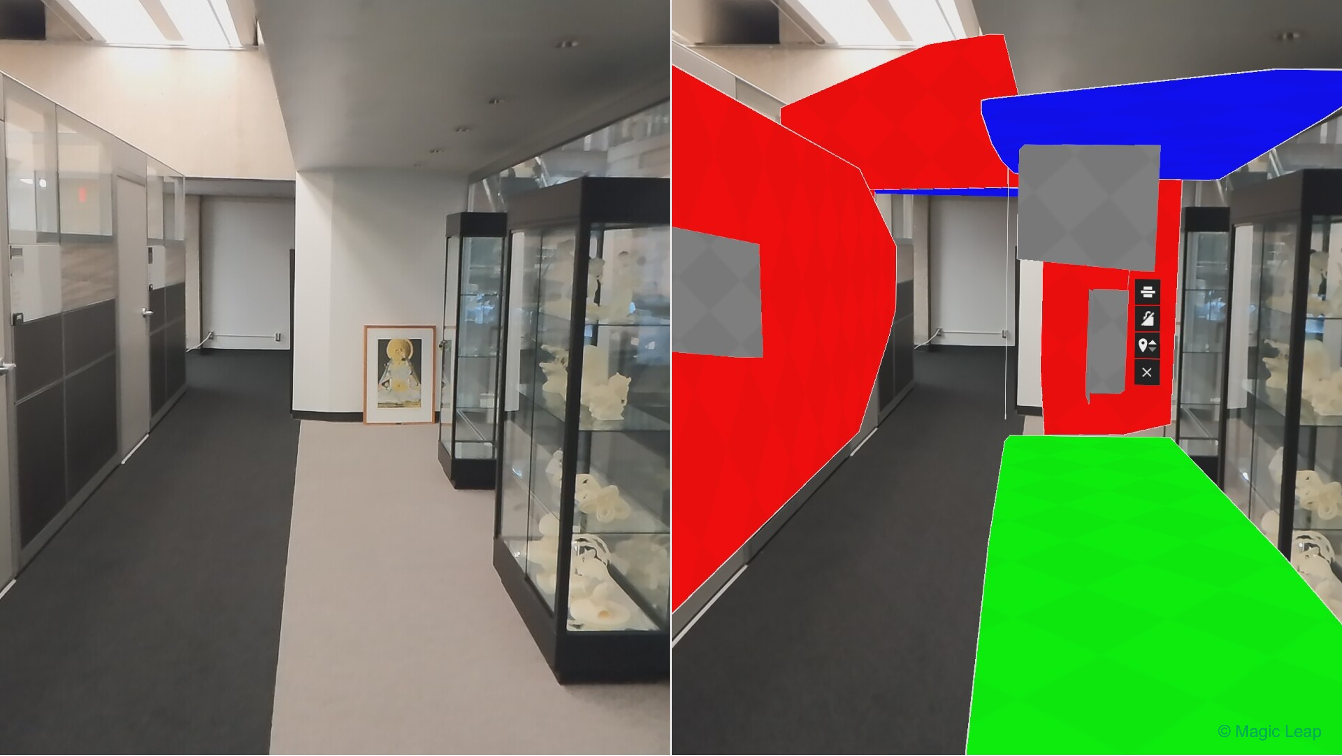
Plane detection identifies and tracks approximately flat surfaces in the physical environment. In AR Foundation, AR Plane Manager creates an ARPlane trackable for each plane reported by the active provider. A plane includes a pose, dimensions, alignment, classification where supported, and boundary points that describe its detected extent. A detected plane, a raycast hit, and an anchor serve different roles. A plane describes a tracked flat region. A raycast returns a candidate pose where a ray intersects a supported trackable. An anchor stabilizes a confirmed pose after placement. Raycast-based placement was implemented on mobile in E3 Mobile AR: Spatial Awareness; anchoring that pose is covered in E5 Mobile AR: Anchors.
Planes are useful because many engineering tasks naturally occur on flat surfaces: a component is placed on a workbench, a machine footprint is displayed on a floor, a task panel is mounted to a wall, or a clearance zone is drawn around a workstation. However, a plane remains a simplified representation. It does not reproduce curved edges, holes, clutter, or the detailed shape of the physical object that produced it.
Key Concepts
The following concepts determine how plane-based placement behaves:
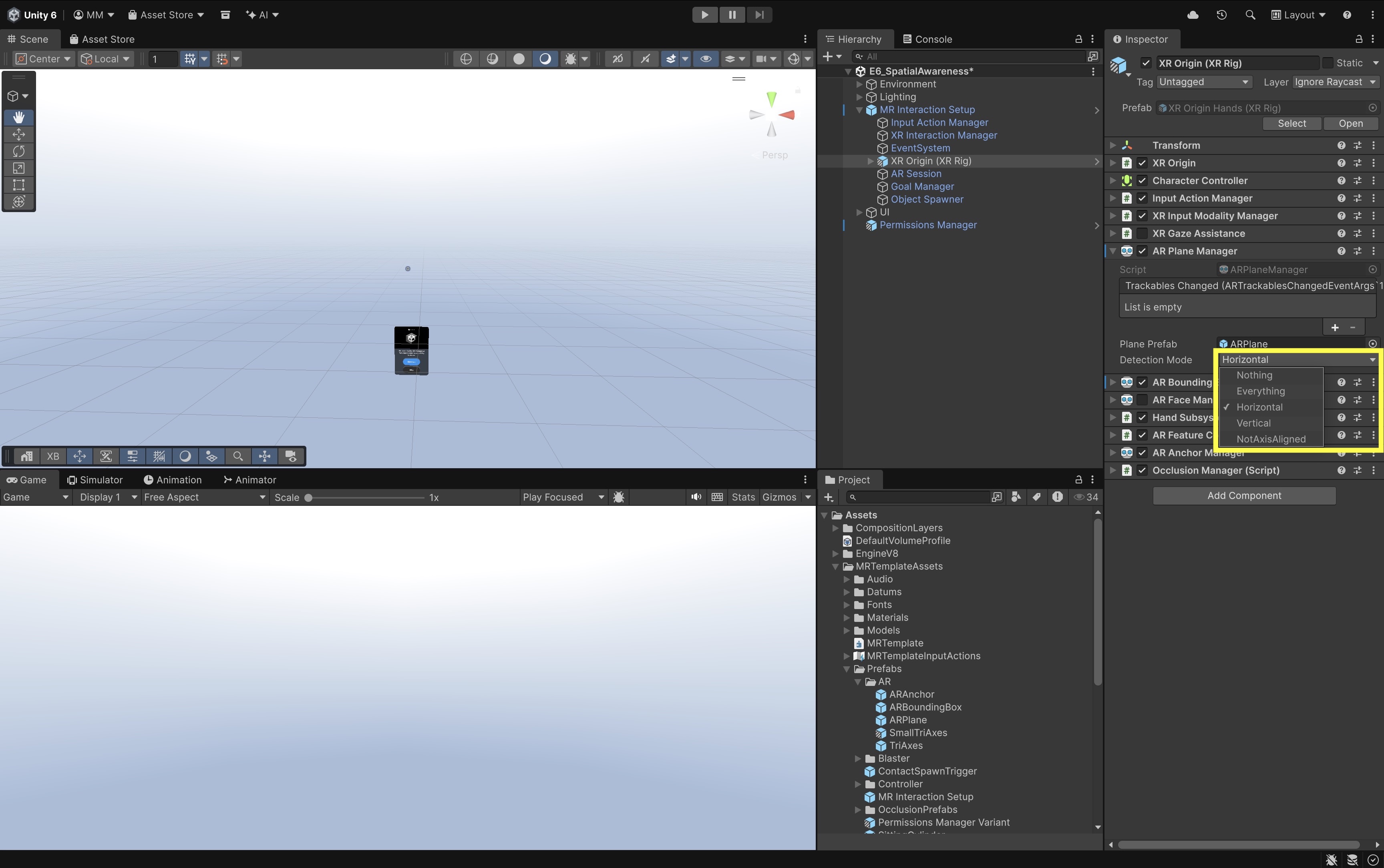
- Detection Mode: Requests horizontal, vertical, all, or no plane alignments. Request only the alignments needed by the application because additional detection can increase visual clutter and platform work.
- Plane Pose: Defines the plane’s tracked position and orientation.
- Boundary: Defines the polygonal extent of the detected surface. Placement inside the boundary is usually more reliable than placement on an infinite mathematical plane.
- Classification: May identify a plane as a floor, table, couch, wall, ceiling, or another category. Classification support varies and should not be treated as universally available.
- Plane Prefab: Controls how each detected
ARPlaneis visualized and whether it includes a renderer, collider, or debug information. - Raycast: Finds where an input ray intersects a supported trackable. A raycast provides a candidate pose; it does not by itself create persistent content or guarantee stability.
- Plane-Aware Transformation: Constrains a grabbed object so it moves along a detected plane instead of moving freely through space.
On the course hardware, plane and mesh information depends on the user’s physical-space setup and scene-understanding permission. Complete Space Setup or equivalent environment setup when required by the active provider before testing and include at least one clear horizontal work surface.
Configure AR Plane Manager
This is the primary hands-on plane tutorial in E6. Work in E6_SpatialAwareness and use the managers already present in the MR Template scene.
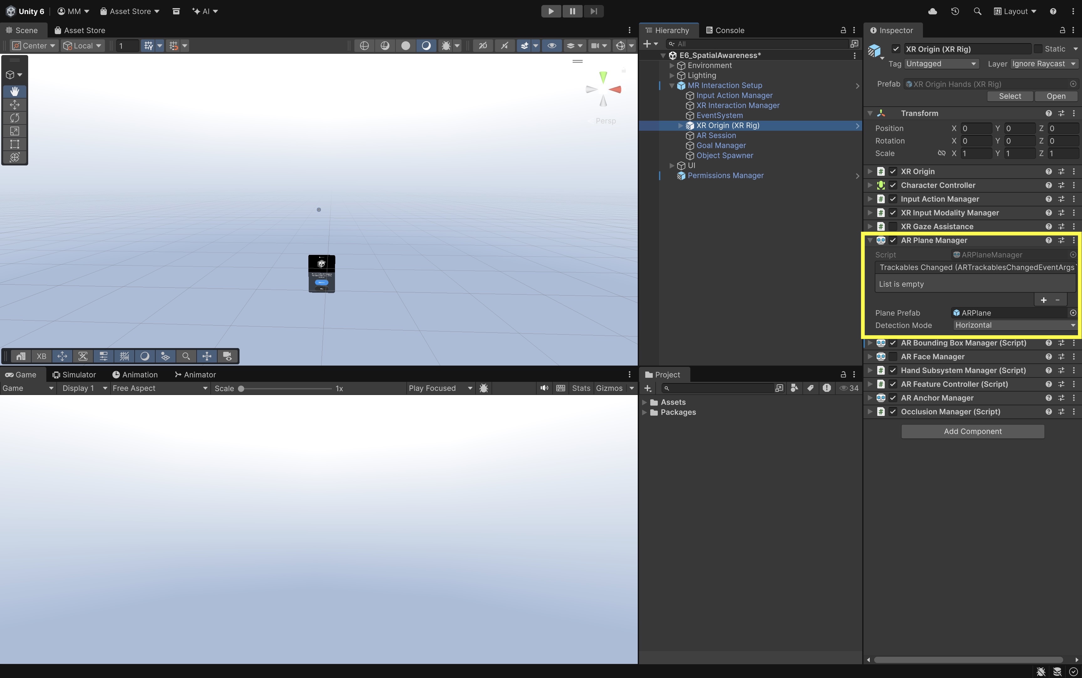
- Locate
AR Plane Manager:- Expand
MR Interaction Setup. - Select
XR Origin. It contains theAR Plane Manager. - Recognize that
AR Plane Manageris an AR Foundation trackable manager: it subscribes to the plane subsystem, instantiates a prefab for each reported plane, and updates or removes trackables as the provider changes its environmental model.
- Expand
- Inspect the Plane Prefab field:
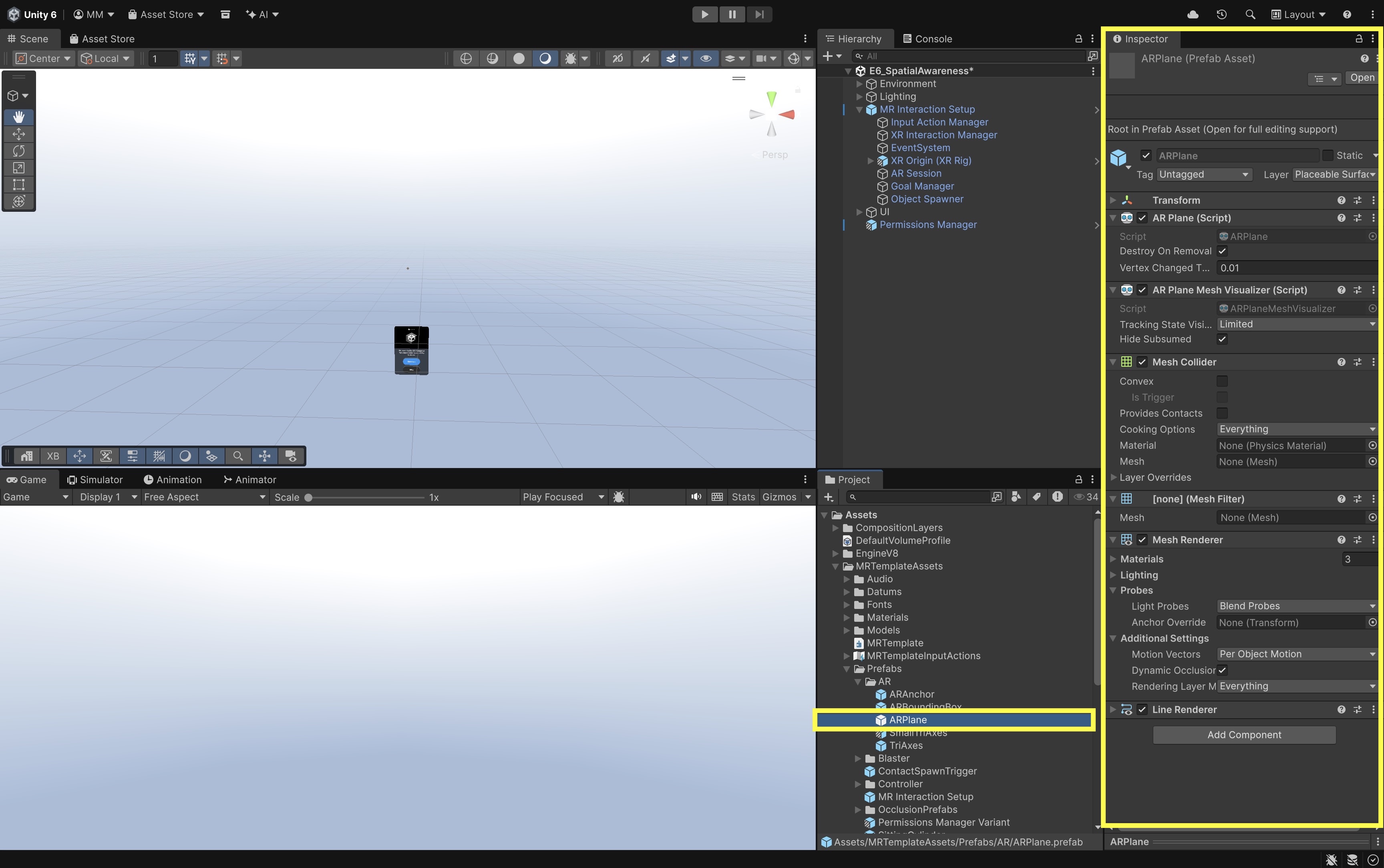
- In the Inspector, locate the
Plane Prefabassignment. - Open the assigned prefab in the Project window.
- Identify its
AR Plane,AR Plane Mesh Visualizer,Mesh Collider,Mesh Filter,Mesh Renderer, and other visualization components supplied by the template.
- In the Inspector, locate the
- Inspect and explain Detection Mode:
- Review the
Detection Modesetting. - Start with horizontal planes for the tabletop activity.
- Enable vertical or other alignments only when the session specifically needs walls, ceilings, or additional categories supported by the active provider.
- Review the
- Review ARPlane trackable data:
- Select a live
ARPlaneinstance during Play Mode or deployment. - Inspect its pose, extents, boundary polygon, alignment, classification where exposed, and
trackingState. - Note that boundary updates, merges, resizing, and removal are normal provider behaviors as the room is scanned.
- On the plane prefab, locate the components responsible for drawing the boundary, filled surface, classification label, or debug text.
- Confirm whether visualization is intended for development only or for end-user placement feedback.
- Keep the plane renderer enabled while learning.
- Use a subtle transparent material rather than an opaque surface that hides the real workspace.
- Select a live
- Verify permissions and room setup:
- Select
PermissionsManager. - Confirm that the scene requests the provider’s required scene-understanding permission.
- Complete physical-space or room setup on the standalone device when required.
- Enable
AR Plane Manageronly after permission succeeds when the active provider requires it. - Confirm that denied permission has a visible recovery path rather than silently failing.
- Select
- Spawn custom prefabs on detected planes:
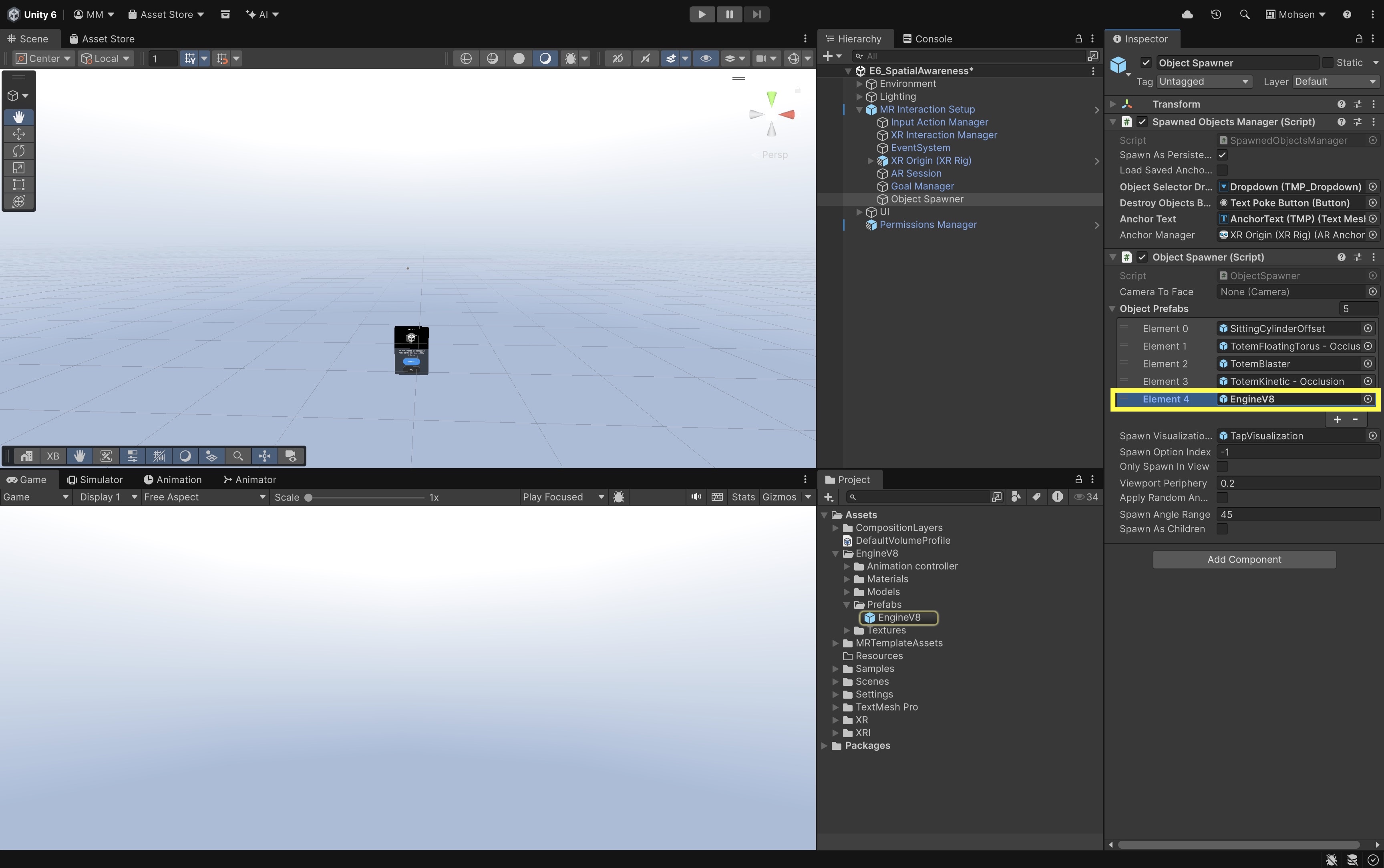
- To use Engine V8, Drone Assembly, or another prepared engineering prefab, add it to the
Object Spawneror replace the visual child of an existing sample totem prefab. - Preserve the base
XR Grab Interactable,XR General Grab Transformer, collider, and affordance components already used by the sample. - Correct only the engineering model’s local scale, pivot, and orientation.
- To use Engine V8, Drone Assembly, or another prepared engineering prefab, add it to the
- Deploy and scan the physical environment:
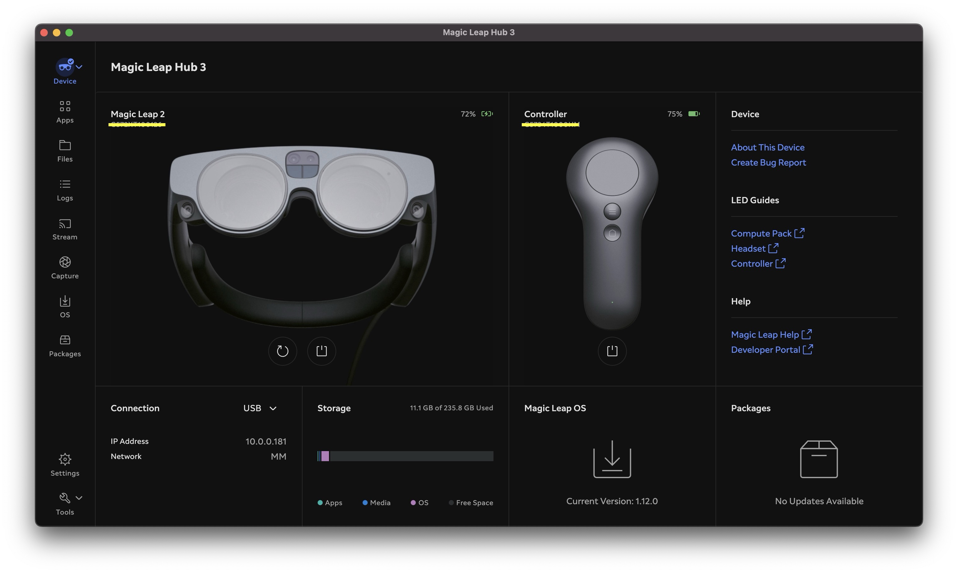
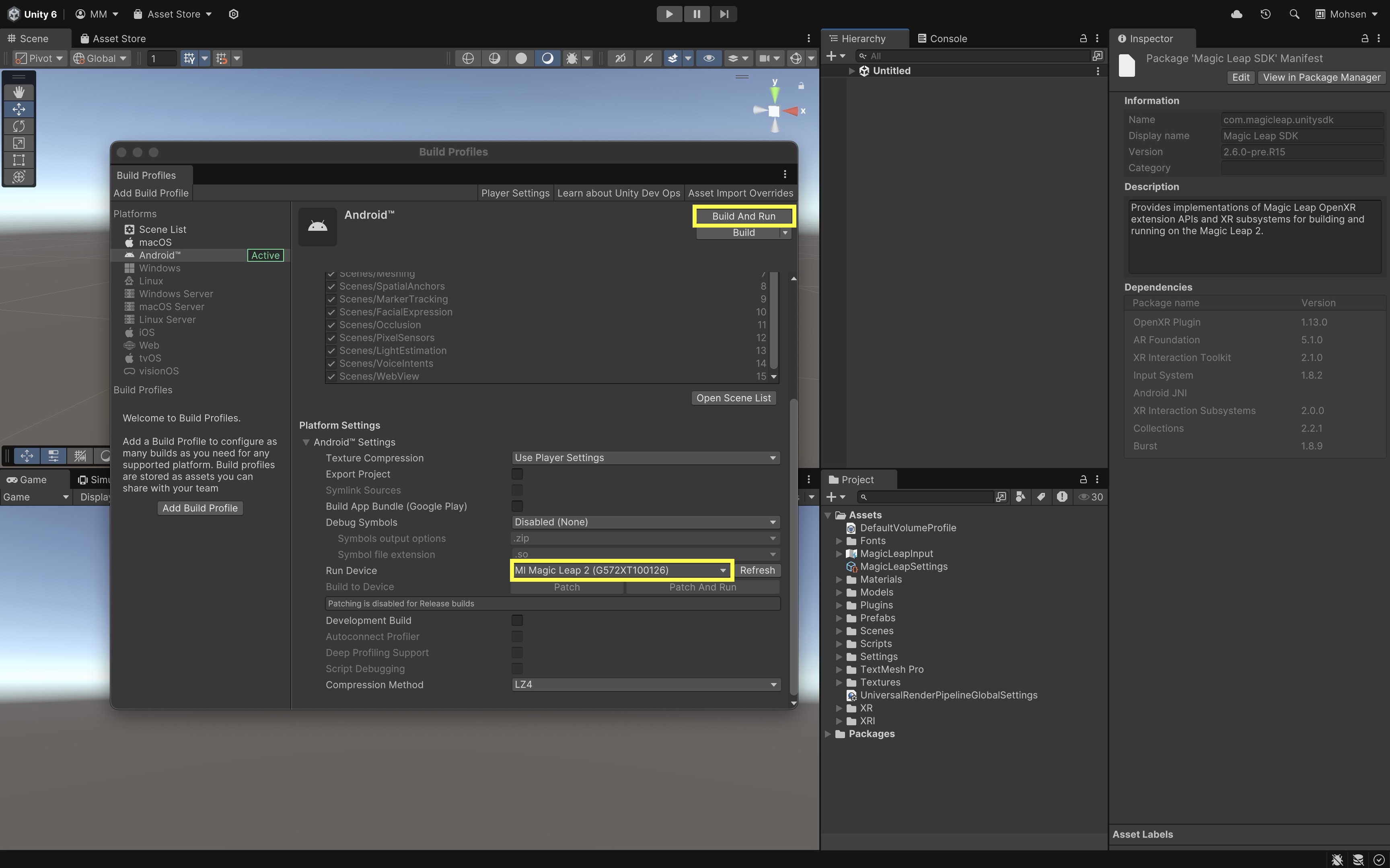
- Build and run the scene on the target headset.
- Look slowly around the prepared room.
- Observe planes being added, updated, merged, resized, or removed as the system receives more information.
- Verify that the intended table or floor appears as a detected plane with a plausible boundary.
- Walk around the surface and confirm that the plane remains understandable from multiple viewpoints.
- Reduce or disable debug visualization:
- After placement testing, hide or disable plane visualization unless users need to see available placement areas.
- Production experiences usually hide debug planes once content is confirmed.
- Leaving
AR Plane Managerenabled can support repositioning and additional placement. - Disabling detection after placement can reduce platform work and visual clutter when no further surface discovery is needed.
A plane manager can exist and remain enabled even when the provider returns no planes. Always distinguish component configuration from runtime feature availability and permission.
Meshing
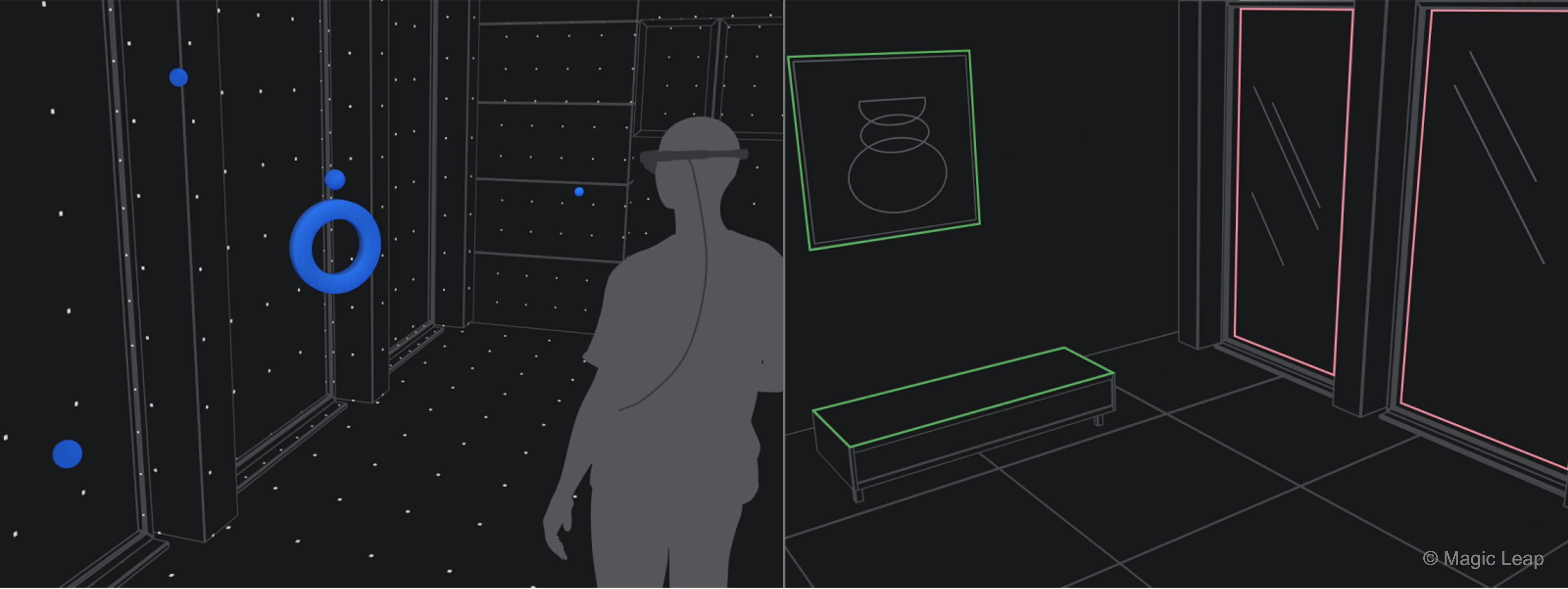
Meshing represents the physical environment as connected triangle geometry. Whereas a plane approximates a broad flat region, a mesh can represent irregular shapes, corners, sloped surfaces, and the boundaries between several physical structures. In AR Foundation, AR Mesh Manager receives mesh data from the active provider and creates Unity meshes from that data.
Meshing can support spatial debugging, visual clearance review, approximate physical interaction, path planning, and geometry-based occlusion. It can also increase CPU, GPU, and memory costs, especially when a dense mesh is rendered or used for physics. Environmental meshes should therefore be enabled and configured for a specific purpose rather than added to every scene by default.
Key Concepts
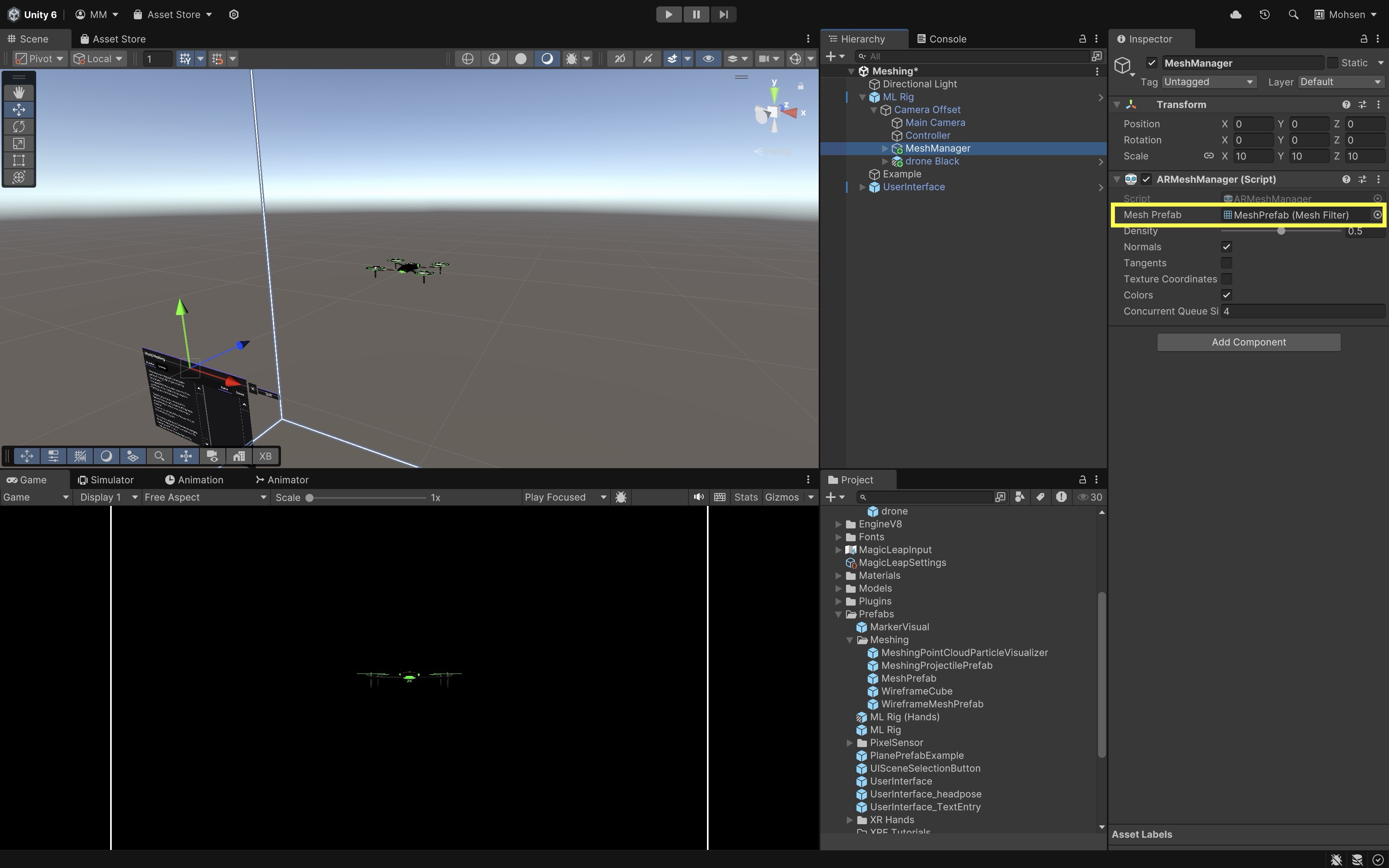
AR Mesh Manager must be attached to a child GameObject of the XR Origin. It uses a mesh prefab as the template for each generated mesh chunk. That prefab must contain a MeshFilter and can optionally contain a MeshRenderer, material, and MeshCollider.
Important settings and design choices include:
- Mesh Prefab: Defines how each generated mesh chunk is rendered and whether it participates in physics.
- Density: Controls requested tessellation from low to high where the provider supports it. Higher density can represent more detail but increases processing and memory.
- Normals: Needed for conventional lighting. Disable them when the mesh is used only for depth or simple debug visualization and the provider permits it.
- Tangents: Needed by some normal-mapped shaders. They are usually unnecessary for a simple environment debug mesh.
- Texture Coordinates: Needed only when the mesh material samples textures using UVs.
- Colors: Needed only when the provider supplies and the shader uses vertex colors.
- Concurrent Queue Size: Controls how many mesh-conversion jobs can be processed concurrently. Larger values can improve throughput but increase resource use.
- Mesh Collider: Allows virtual physics objects to collide with the represented environment. Collider generation is expensive and the geometry is not safety-certified.
For the active provider, environmental mesh data may depend on the user’s physical-space setup and scene-understanding permission. If that setup is incomplete,
AR Mesh Managercan be correctly configured and still receive no mesh data.
Planes vs. Meshes
| Question | Plane representation | Mesh representation |
|---|---|---|
| Is the surface flat? | Assumes yes | Can represent irregular geometry |
| Is placement simple? | Yes; ideal for tabletop and floor placement | More complex; raycasts and normals can vary |
| Is detailed collision possible? | Only a flat approximation | Possible with MeshCollider, at added cost |
| Is occlusion possible? | Coarse plane-based occlusion | More complete geometry-based occlusion |
| Is semantic meaning included? | Classification may be available | Geometry alone does not guarantee semantics |
Configure AR Mesh Manager
Add meshing without disturbing the existing camera, input, plane, and anchor managers.
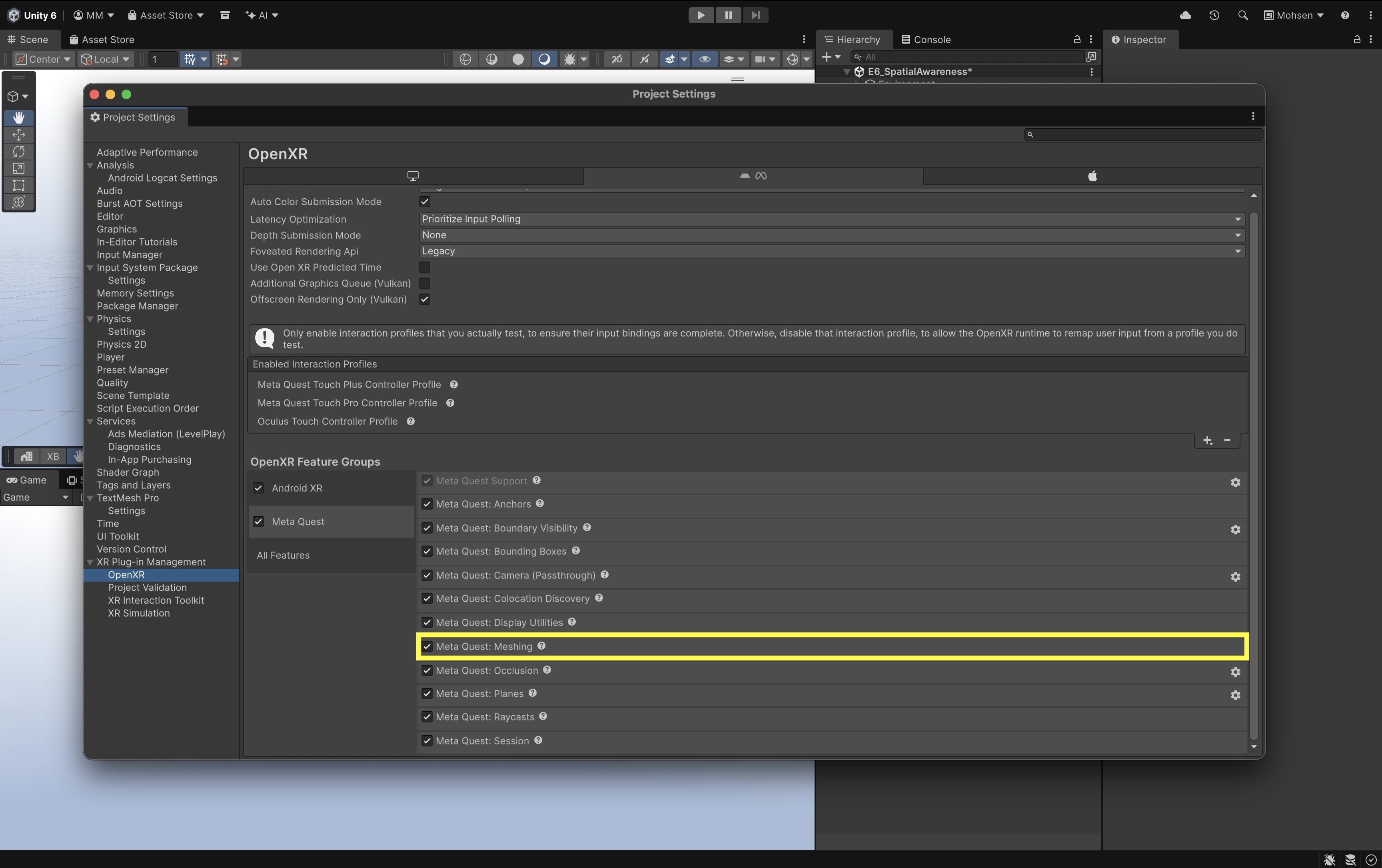
- Verify provider support:
- Open
Edit > Project Settings > XR Plug-in Management > OpenXR. - In the active provider feature group, verify that meshing or scene-mesh support is enabled.
- Keep unrelated experimental features disabled.
- Open
- Check physical-space setup and permission:
- Complete the headset’s physical-space or room setup when required.
- Ensure
PermissionsManagerrequests the scene-understanding permission needed by the provider. - Follow the permission-dependent manager activation pattern from the MR Template orientation before enabling
AR Mesh Manager. - Provide feedback when the permission is denied.
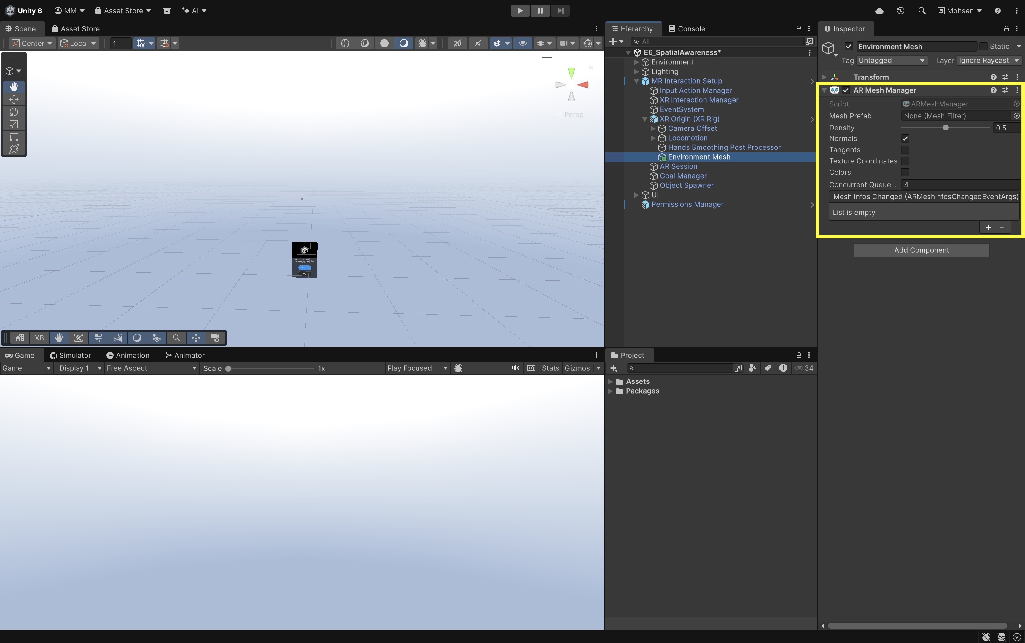
- Locate or add AR Mesh Manager:
- Expand the XR Origin in
MR Interaction Setup. - Locate an existing
AR Mesh Managerchild if the template already includes one. - If absent, create a child named
Environment Meshand addAR Mesh Managerto that child. - Review
Densityand start with a conservative value where exposed. - Disable
Tangents,Texture Coordinates, andColorswhen the selected material or application does not use them. - Review
Concurrent Queue Sizeand keep the default unless profiling shows a need to change it.
- Expand the XR Origin in
- Create and assign a simple mesh prefab:
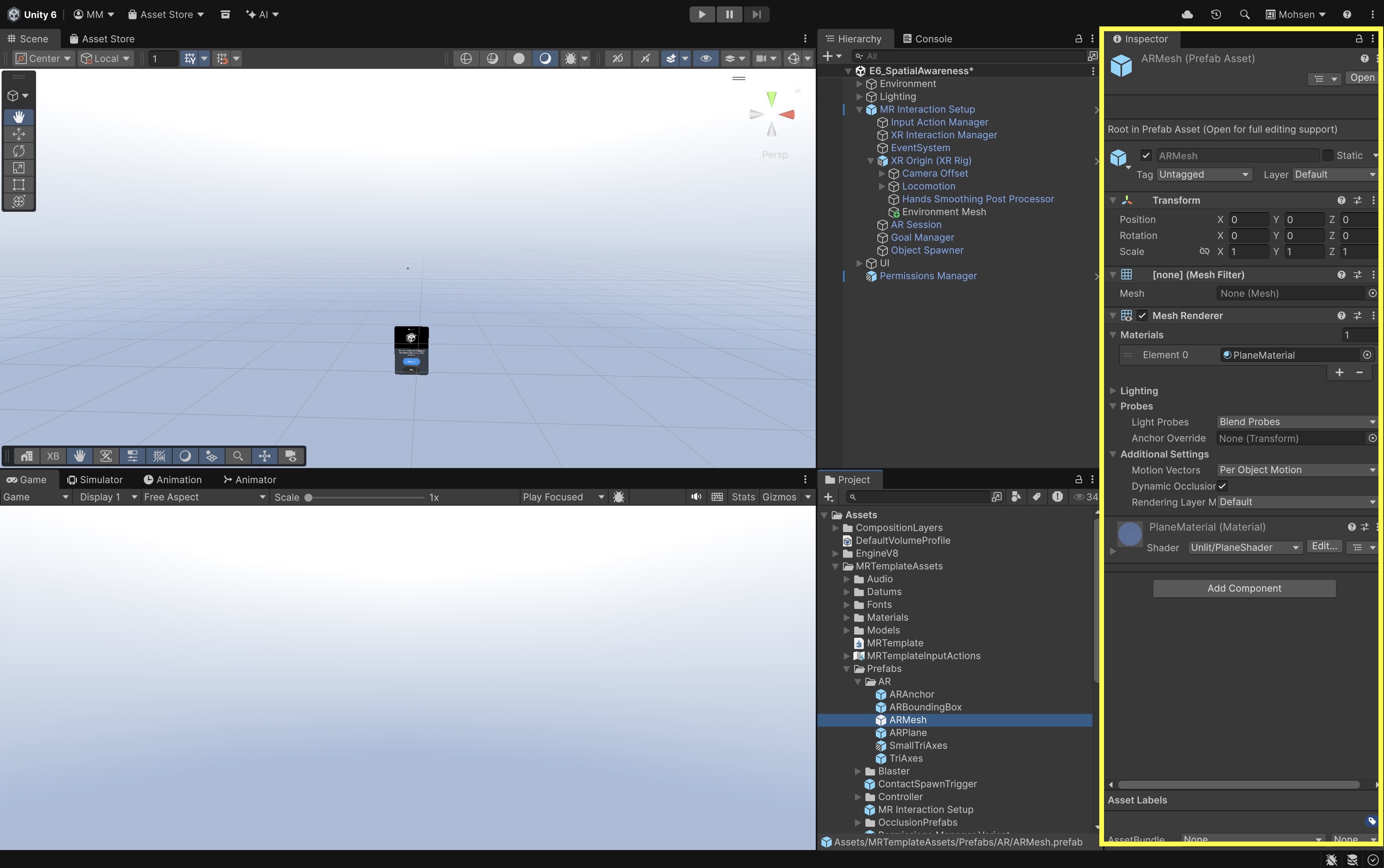
- Create an empty GameObject and add a
Mesh Filter. Name it ARMesh. - To visualize the mesh during testing, also add a
Mesh Rendererand assign a simple semi-transparent debug material. - Save the GameObject as a prefab, remove the scene instance from the Hierarchy, then select
AR Mesh Managerand assign that prefab toMesh PrefabofEnvironment Mesh.
- Create an empty GameObject and add a
- Test virtual-object collision with the environmental mesh:
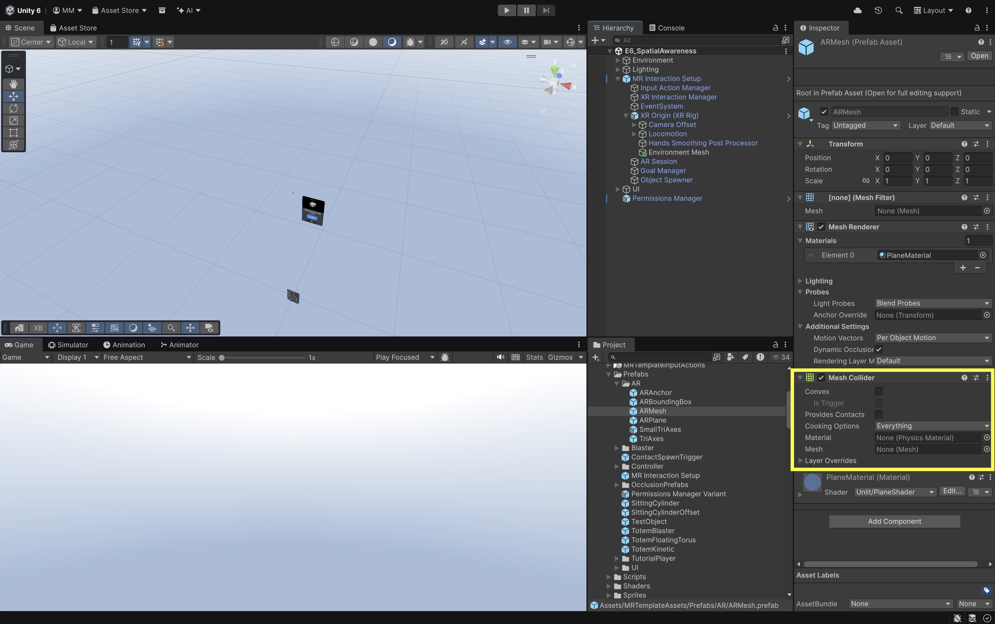
MeshRendereris for visualization. A semi-transparent unlit debug material is sufficient for development review.MeshCollideris optional and can be expensive. Do not add it unless approximate collision is required.- Add a
Mesh Colliderto theARMeshprefab so generated mesh chunks can participate in Unity physics. - Leave the
Convexbox unchecked for the environment mesh so collisions accurately follow its concave room geometry. - Confirm that the spawned sample objects includes a
Rigidbodyand an appropriate collider. - Build and run the scene, scan a physical surface such as a sofa, chair, or table, and wait until its mesh is generated.
- Use the
Object Spawnerto create a virtual object, hold it above the mapped surface, and release it. - Observe how the object falls onto and rests against the reconstructed surface. For example, dropping a virtual object onto a physical sofa can make the collision appear realistic because the environmental mesh provides an approximate physical surface.
- Disable the Mesh Renderer to hide the debug mesh while keeping the Mesh Collider enabled, then repeat the test to experience the collision without seeing the reconstructed geometry.
- Deploy and observe mesh generation:
- Build and run the scene on the standalone device.
- Move slowly around the prepared room.
- Confirm that mesh chunks represent the floor, table, walls, and other captured geometry.
- Observe seams, gaps, coarse regions, and geometry that does not match movable objects.
A prepared assembly model, machine footprint, or clearance volume can be viewed against the environmental mesh to assess approximate spatial relationships. The environmental mesh is a visualization and interaction aid, not a certified measurement or collision model.
Occlusion
Occlusion occurs when a nearer object hides part of a farther object. Correct occlusion is one of the strongest visual cues for depth order. Without it, virtual content is always rendered over the passthrough background, so an object that should be behind a physical table edge may incorrectly appear in front of it. AR systems can implement occlusion from geometry, per-pixel environment depth, human segmentation, hand meshes, or combinations of these sources. This session focuses on configuring AR Occlusion Manager and validating the result on the target headset rather than authoring custom occlusion shaders.
Key Concepts
The two main approaches used in this session are:
- Geometry-based occlusion: A plane or environmental mesh is rendered into the depth buffer but not into the color buffer. The physical environment remains visible through passthrough, while virtual objects behind the depth-only geometry fail the depth test and are hidden.
- Environment-depth occlusion: The runtime provides a per-pixel estimate of the distance from the viewer to the physical environment. Compatible shaders or renderer features compare physical depth against virtual depth and hide virtual pixels that should appear behind the real environment.
| Approach | Advantages | Limitations |
|---|---|---|
| Geometry-based (planes) | Builds on plane geometry already used for placement; easy to debug with a visible material; works with normal virtual-object materials when the occluder writes depth | Occludes only where plane geometry exists; cannot represent irregular or vertical detail beyond coarse flat regions |
| Geometry-based (mesh) | Uses reconstructed room geometry for depth-only occlusion; same debug workflow as plane-based occlusion | Occludes only where mesh geometry exists; does not represent moving people or objects; thin, transparent, reflective, or recently moved objects may be missing |
| Environment-depth | Responds to changing depth in the camera view; does not require complete triangle geometry for every surface; can produce more natural edges around irregular objects | Requires provider, device, graphics API, permission, and shader support; can be noisy near boundaries, hands, thin objects, and reflective surfaces; higher quality or smoothing can increase computation or latency |
| Optional (hand mesh / removal) | Can improve virtual/physical hand composition when supported | Depends on device, hand-tracking setup, and project configuration |
Plane and mesh occlusion suit coarse static geometry; environment depth needs compatible shaders and active provider support at runtime. Hand mesh or hand removal is optional and configuration-dependent—not guaranteed in every build.
Configure AR Occlusion Manager
- Verify occlusion support:
- Confirm that the active provider supports the occlusion subsystem and the environment-depth or mesh-occlusion features needed by the project.
- Enable the provider’s occlusion OpenXR feature for the active build target when required.
- Use a supported graphics API.
- Locate or add AR Occlusion Manager:
- Select the
Main Cameraunder theXR Origin. - Confirm that
AR Camera Manageris present and enabled. - Add
AR Occlusion Managerto the camera if it is absent. - On OpenXR head-mounted displays, the project may also require
AR Shader Occlusionso depth textures and projection data become available to compatible shaders. Follow the active template’s camera setup.
- Select the
- Inspect environment-depth and preference fields:
- Review the
Environment Depth Modeoptions exposed by the installed package version. - Review
Occlusion Preference Modeand any temporal-smoothing option when supported. - Understand the difference between requested and supported modes.
AR Occlusion Managerobtains depth-related textures from the provider when available.- Compatible shaders or renderer features must sample those textures or consume the depth information through the project’s occlusion path.
- Review the
- Deploy and observe occlusion:
- Build and deploy the scene with occlusion enabled using the settings configured above.
- Use the
Object Spawnerto create a sample virtual object in the room. - Move around the object and place it so part of it should pass behind a physical surface such as a table edge, shelf, or wall.
- Observe whether the virtual content is hidden behind physical objects as expected. Results depend on the active occlusion path, provider support, and the manager settings you selected.
Occlusion helps engineering content respect the physical workspace during review. An assembly model, machine footprint, clearance volume, or instruction panel can appear correctly hidden when it passes behind a table, shelf, wall, or other physical occluder, making spatial relationships easier to judge during layout, maintenance, or training tasks.
Validate the Experience
A spatial-awareness feature is not complete when it works in the Inspector. The final evaluation must occur on the target headset in the physical environment for which the activity was designed.
Validation Checklist
| Test area | What to verify |
|---|---|
| Passthrough | The physical environment is visible without an unintended black background or duplicate camera. |
| Tracking | Head motion produces a stable viewpoint without obvious stutter or incorrect origin behavior. |
| Permissions | Denied scene-understanding permission produces understandable feedback and recovery. |
| Room setup | Required physical-space or room setup was completed before spatial features were tested. |
| Plane detection | At least one intended horizontal surface is detected and its boundary is plausible. |
| Object manipulation | The sample object can be selected, grabbed, moved, and released using its configured XRI grab components. |
| Scale and pivot | The placed content has believable scale and rests on the surface without obvious floating or penetration. |
| Environmental mesh | Mesh chunks appear where supported and their limitations are visible. |
| Mesh performance | Density, rendering, and optional collision do not create unacceptable frame-time or memory cost. |
| Occlusion | At least one supported occlusion path hides virtual content behind a real occluder from multiple viewpoints. |
| Shader compatibility | Engineering-model materials respond correctly to the selected occlusion path where tested. |
| Registration | Content remains visually coherent while the user changes position and viewing height. |
| Unsupported-feature fallback | Missing mesh, depth, or classification support degrades gracefully without breaking the session. |
| Standalone performance | Frame rate, thermal behavior, and load time remain acceptable for the engineering task. |
| Physical safety | The user can see the table, floor, cables, people, and nearby hazards while interacting. |
| Spatial audio reuse | Reuse the spatial-audio and feedback practices from D6 Haptics and Spatial Audio in VR when the passthrough AR application needs localized alerts or confirmation cues. |
Troubleshooting
- Passthrough does not appear:
- Confirm that the intended OpenXR provider and camera feature are enabled.
- Confirm that
AR Camera Manageris present and enabled on the tracked Main Camera. - Confirm that the camera background uses zero alpha as required by the provider.
- Check the selected URP preset and project validation.
- Remove any duplicate camera, XR Origin, or manually added passthrough rig.
- No planes are detected:
- Complete the physical-space setup and include a clear table or floor.
- Confirm that
AR SessionandAR Plane Managerare enabled. - Confirm that the provider’s plane feature and required permission are enabled.
- Begin with horizontal detection.
- Test in a standalone build rather than assuming Editor behavior represents the device.
- The sample object does not move as expected:
- Compare the selected prefab with an original sample totem such as Totem Floating Torus.
- Confirm that the base
XR Grab Interactable,XR General Grab Transformer,Rigidbody, andColliderremain configured. - Confirm that the user is grabbing the base rather than an unrelated child object.
- Confirm that input interactors and the interaction manager are active.
- Remember that standard XRI grab movement does not automatically constrain content to detected planes unless a separate surface-constraining component is configured.
- No environmental mesh appears:
- Confirm that the provider’s meshing feature is enabled.
- Complete physical-space setup and grant scene-understanding permission.
- Confirm that
AR Mesh Manageris a child of the XR Origin. - Confirm that its Mesh Prefab contains a
MeshFilter. - Switch temporarily to a visible debug material.
- Check whether the provider supplies saved scene mesh rather than live reconstruction.
- Occlusion does not work:
- Confirm that the requested occlusion mode is actually supported at runtime.
- For environment-depth occlusion, verify the OpenXR feature, graphics API, permission,
AR Occlusion Manager,AR Shader Occlusionwhere used, and compatible shader or renderer feature. - For geometry-based occlusion, confirm that occluding mesh or plane geometry exists and writes depth before virtual content renders.
- Test on the target headset; do not diagnose depth quality only from the Editor.
- Standalone performance is poor:
- Reduce mesh density and remove unnecessary normals, tangents, colors, or UVs.
- Disable visible mesh and plane rendering after debugging.
- Avoid
MeshColliderunless the task requires it. - Inspect engineering-model texture sizes, material count, geometry, animation, and real-time lighting.
- Remove unrelated sample objects after the spatial-awareness workflow is stable.
- Profile on the target hardware before choosing an optimization.
Key Takeaways
- Spatial awareness in passthrough AR is only as reliable as the physical environment, headset sensors, active provider, permissions, and room setup.
- The Unity MR Template provides the baseline scene, interaction infrastructure, and AR Foundation managers used throughout E6–E7.
- Passthrough AR combines a camera-mediated physical view with virtual content; it is not equivalent to unobstructed natural vision or optical see-through AR.
- Planes provide environmental surfaces that can support placement workflows, while raycasts can identify candidate poses where supported; meshes and occlusion improve realism where supported, but meshing, depth, and related features remain provider-dependent and are not validated safety or collision systems.
- Prepared engineering assets can replace sample content without rebuilding the spatial-awareness workflow; final behavior still requires on-device validation for registration, performance, physical safety, and unsupported-feature fallback.