E3. Mobile AR: Spatial Awareness

Learning Outcomes
- Explain how AR applications achieve spatial awareness on mobile devices. Before class, review how feature points, planes, meshes, occlusion, and environment probes work together, and connect these ideas to the XFactory robot examples.
- Describe the role of point clouds in AR tracking and localization. In preparation, read about how feature points form point clouds and how to check optional identifiers and confidence values safely at runtime.
- Explain the purpose of plane detection in mobile AR. Ahead of the session, focus on how flat surfaces support tap-to-place spawning and obstacle-aware robot behavior using plane alignment.
- Differentiate between plane detection and meshing in AR. Study how meshing supports richer geometry and collision, while recognizing that meshing is provider- and device-dependent.
- Identify which spatial-awareness features are provider/device-dependent. Be ready to explain why classification, meshing, occlusion, and environment probes may not be available on every phone or tablet.
- Describe occlusion and environment probes and their limits. Learn how depth-based hiding and reflection probes improve realism without replacing validated safety or navigation systems.
- Evaluate how lighting, texture, reflective surfaces, device sensors, and provider support affect tracking, planes, meshing, occlusion, and environment probes. Come ready to discuss real-environment testing, not Editor-only assumptions.
What Is Spatial Awareness?
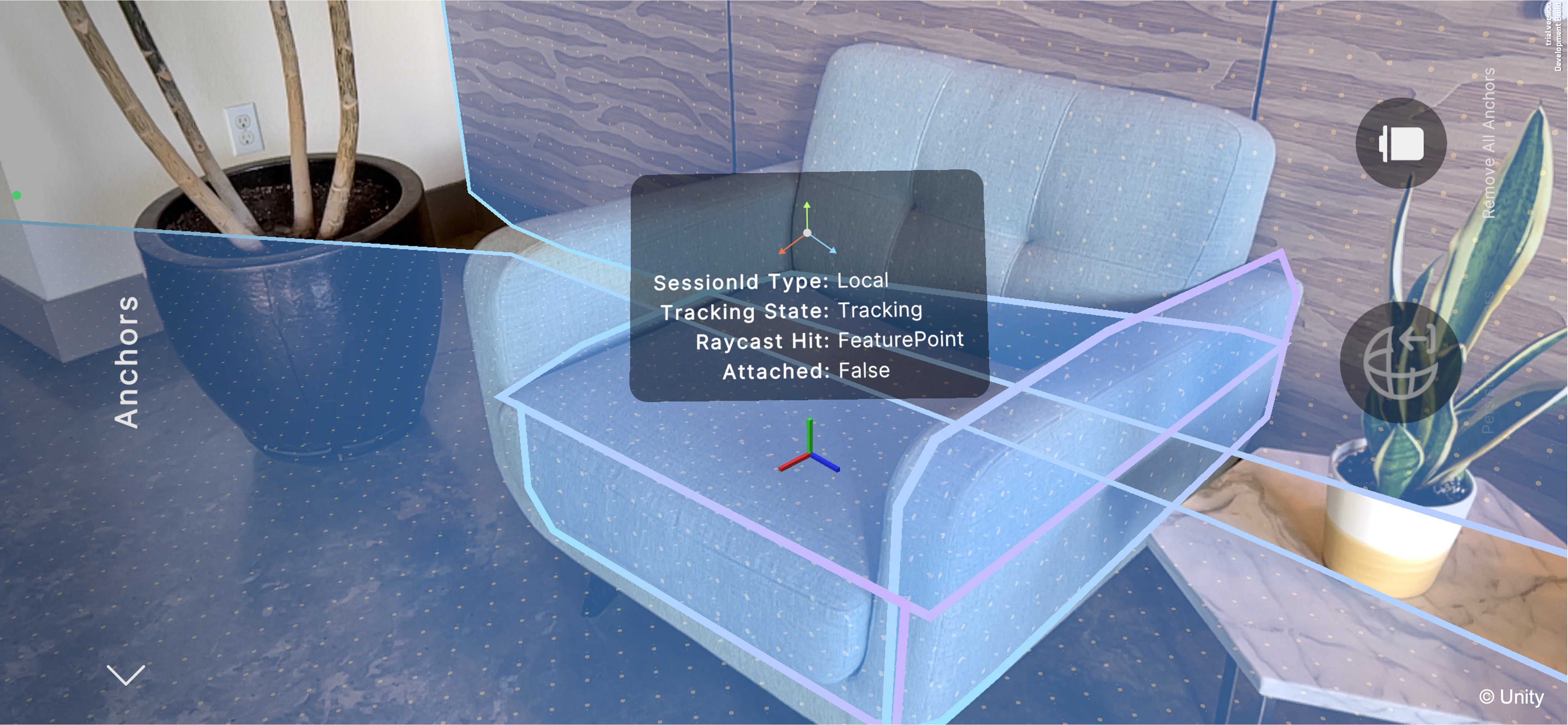
AR relies on accurate perception of the physical environment to convincingly blend virtual content with the real world. Spatial awareness is the set of techniques and data structures that enable an AR app to interpret its surroundings. Point clouds, planes, meshing, occlusion, and environment probes are provider-dependent. A phone, tablet, or headset may support some of these features but not others, and support can vary by model, OS, sensor hardware, and provider settings. By extracting and organizing information about points, surfaces, volumes, and lighting in the scene, spatial awareness enables:
- Stable Tracking and Anchoring: Feature points and point clouds provide the reference markers that keep virtual objects locked in place, even as the camera moves. Point clouds (via the
ARPointCloudManager) capture and visualize these feature points, creating the underlying spatial map AR uses for robust pose estimation. Imagine a virtual quadruped robot in AR navigating a physical room. The robot can use feature points to stabilize its initial placement on the floor. You can visualize the point cloud to verify tracking quality under different lighting or surface conditions. - Contextual Interaction: Plane detection makes it possible to place virtual furniture on a table, drop characters onto the floor, or snap UI elements to walls. The
ARPlaneManagerdetects, tracks, and classifies horizontal and vertical surfaces—exposing lifecycle events and enabling precise tap-based object placement. The robot can navigate along detected horizontal planes (like the floor) and stop near vertical planes (like walls or cabinets), simulating obstacle-aware, autonomous navigation. Users tap to place the robot at a starting location, and plane detection ensures it’s properly grounded. - Environmental Geometry and Physics: Meshing constructs a 3D representation of the scene’s surfaces, enabling collision detection, pathfinding, and custom physics interactions with real‑world geometry. The
ARMeshManagergenerates and updates a spatial mesh in real time, which your app can use for physics simulation, raycasting, and advanced gameplay logic. Enable mesh reconstruction of the room to help the robot “see” obstacles like chairs or boxes. You can program it to stop or turn when detecting a mesh collision, demonstrating spatial awareness similar to SLAM (Simultaneous Localization and Mapping) in robotics. - Realistic Rendering and Occlusion: Depth and stencil textures (from occlusion) allow virtual objects to hide correctly behind real-world objects, while environment probes capture lighting so digital content reflects and casts shadows coherently. The
AROcclusionManagersupplies per‑frame depth and stencil textures for accurate occlusion. When the robot moves behind a couch or table in the room, occlusion ensures it disappears correctly from the camera’s view, enhancing realism. This helps users perceive the virtual robot as if it truly shares the space with physical objects. - Adaptive Lighting and Reflections: Environment probes sample ambient light and reflections so virtual objects match the scene’s brightness, color temperature, and specular highlights. By placing
AREnvironmentProbecomponents manually or automatically, your app gathers cubemap data to drive dynamic material adjustments for lifelike integration. Add environment probes in the room to dynamically light the robot based on its current location—bright by a window, dimmer near a wall. The robot’s reflective parts (like a metallic head or chassis) will reflect environmental lighting in real time.
The point cloud handles tracking and localization; plane detection finds flat, stable surfaces for placement; and meshing can build richer 3D environment geometry for advanced interaction. On supported devices, occlusion can hide virtual content behind real geometry—but these features must be validated on the target hardware.
Point Clouds
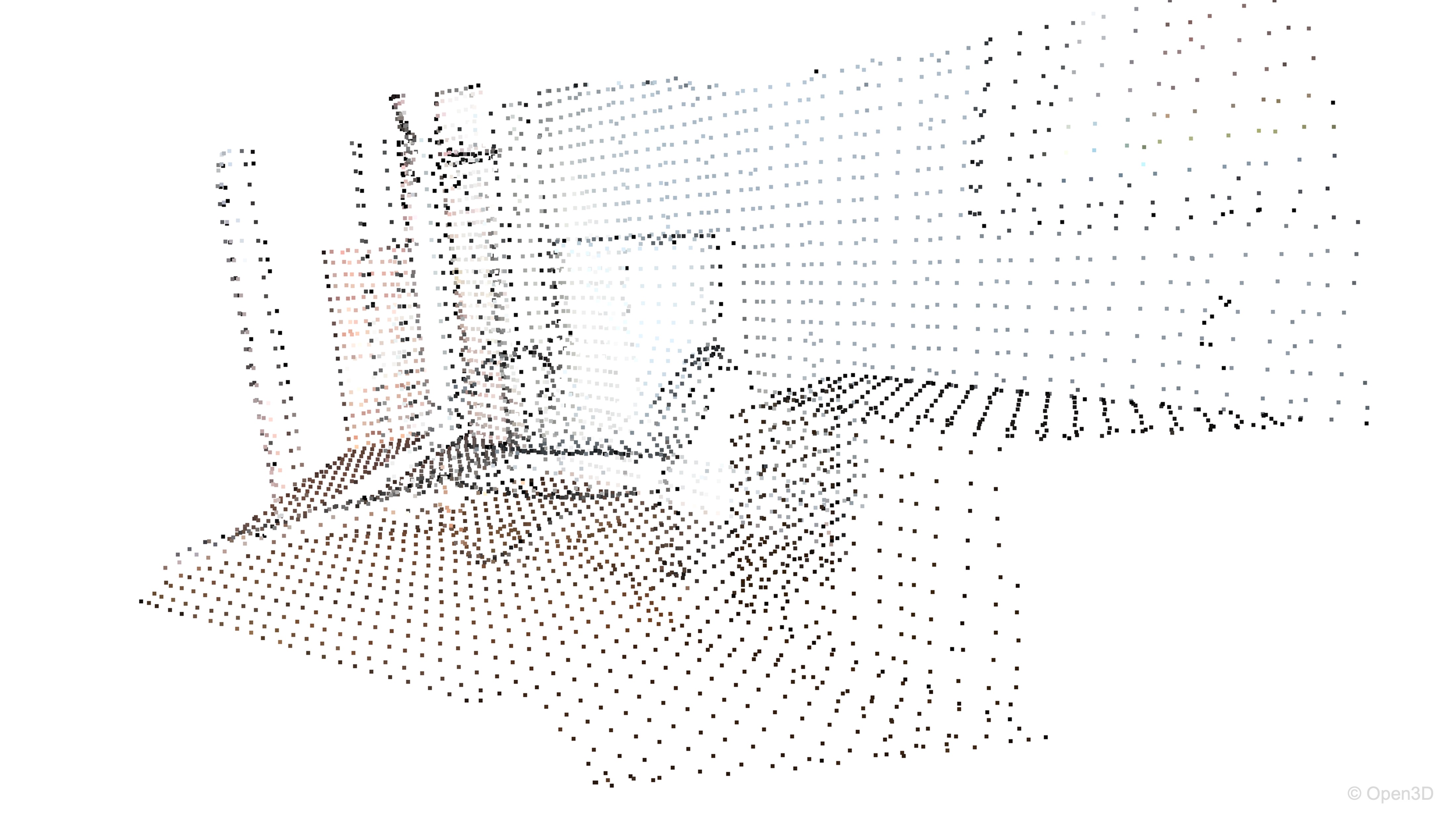
A point cloud in AR represents a continuously updated set of feature points detected in the real environment. These points form the foundation for tracking and localization, allowing the AR device to maintain an accurate sense of its position and orientation over time. Unlike higher-level trackables such as planes or meshes, which interpret the environment’s structure, the point cloud provides the raw spatial data that underpins all other scene understanding. For instance, when visualizing a quadruped robot’s navigation, rendering the room’s point cloud lets users assess whether sufficient, stable feature points exist on the floor and furniture for reliable odometry and waypoint tracking—demonstrating how low-level spatial perception supports high-level behavior in both AR and real-world SLAM systems.
Feature Points
A feature point is a pixel or small region in a camera image that stands out due to high contrast or distinct texture (e.g., the edge of a table, a knot in wood). AR subsystems detect these points because they remain visually stable across multiple frames. By matching feature points frame-to-frame, the AR system calculates how the camera has moved, enabling stable virtual content placement. Each feature point in ARPointCloud provides:
- Position (
Vector3): The 3D coordinates of the point in session space relative to theXR Origin(i.e., the device camera). Checkcloud.positions.HasValuebefore reading positions. These positions form a sparse point cloud that helps the system understand surface geometry and improve scene reconstruction. - Identifier (
ulong, optional): A persistent ID that lets you track the same physical point across multiple frames. Checkcloud.identifiers.HasValuebefore reading identifiers—not all providers supply them. Identifiers are useful when attaching content to specific, consistent points in the world—for example, placing a persistent label next to a machine component. - Confidence (
float, optional): A score indicating the subsystem’s certainty in the point’s stability. Checkcloud.confidenceValues.HasValuebefore filtering on confidence. Confidence values are optional and provider-dependent; do not assume ARKit-style confidence on every device. When available, filtering low-confidence points can reduce noisy visualization or debug overlays.
By subscribing to
ARPointCloudManager.pointCloudsChanged, you can iterate through eachARPointCloudafter checkingpositions.HasValue(and optionallyidentifiers.HasValueandconfidenceValues.HasValue) to record or visualize the 3D coordinates and stability of detected points each frame. This lets you log raw spatial data for debugging, analysis, or SLAM research.
AR Point Cloud Manager
The ARPointCloudManager is responsible for creating, updating, and destroying ARPointCloud trackables in your Unity scene. It inherits from ARTrackableManager, which handles lifecycle events for AR data types.
- Point Cloud Prefab: This is a prefab that visualizes each detected feature point in the real world—typically as small spheres or particles. You can use this to give users a visual sense of how the device is mapping the environment. Developers often customize the prefab to vary the color or size of the points based on confidence or depth, enhancing debugging and user feedback during development.
- Detect Feature Points: A toggle that enables or disables the generation of point clouds from the camera feed. Disabling this can significantly improve performance, especially on lower-end devices. Expose
Detect Feature Pointsin your in-app settings. If users disable it to boost performance, the robot disables autonomous rerouting and relies on manual waypoint taps instead. This feature is especially important in performance-sensitive scenarios such as real-time navigation or mobile multiplayer apps, where excessive tracking overhead can impact frame rates or battery life.
Implementing Point Clouds
Let’s visualize point clouds in AR Foundation and use them to assess tracking quality for the XFactory quadruped robot workflow. Point clouds are most useful for tracking and debugging. For stable object placement, prefer plane raycasts and anchors in the next section. Do not instantiate new marker objects for every point every frame; use the default point cloud visualizer or object pooling.
- Create and Configure a New Scene:
- Open the existing
AR101scene fromAssets/Scenes. - Go to
File > Save Asand name the new sceneWorld Understanding. - Save it in the same folder (
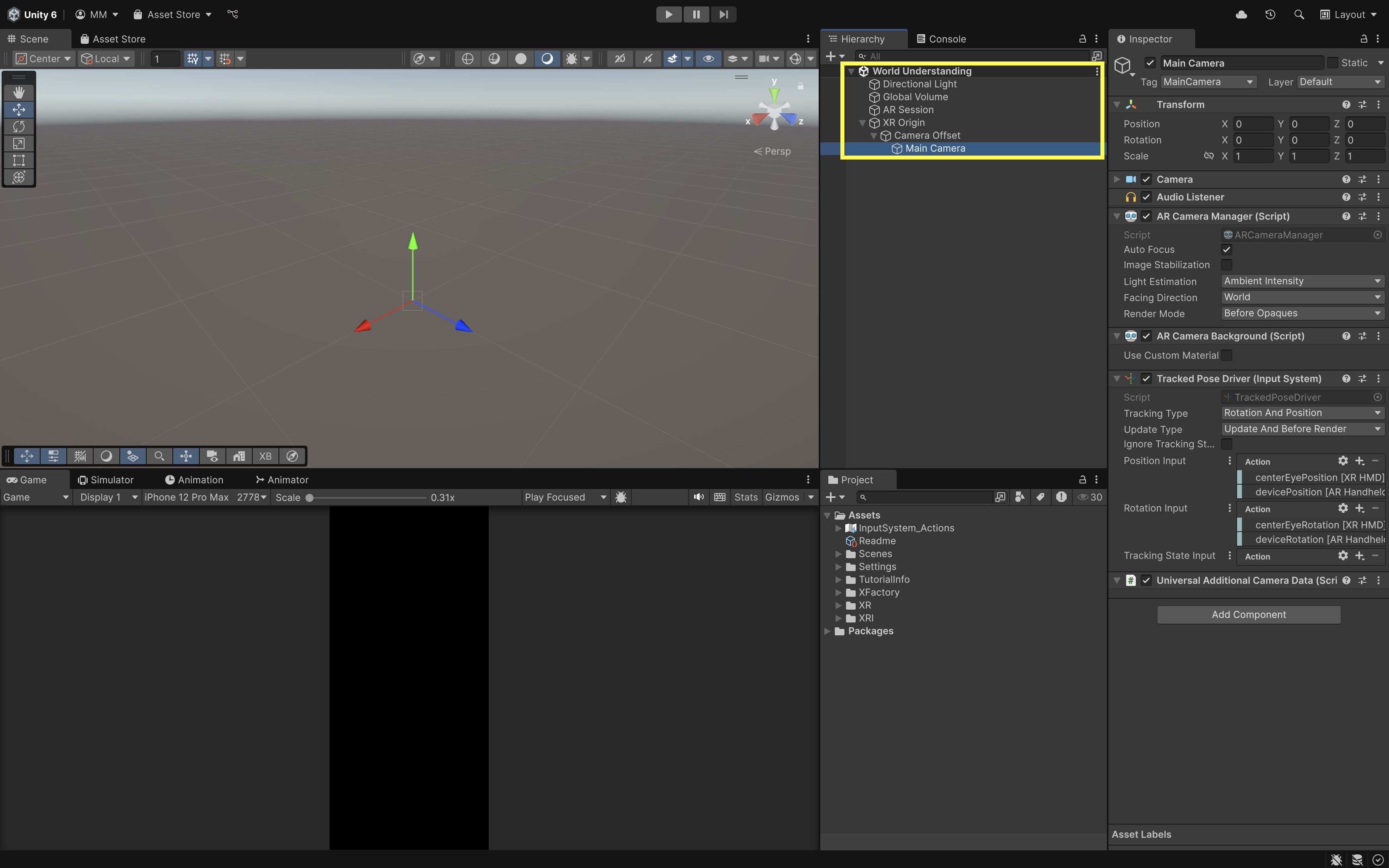
Assets/Scenes/World Understandingor similar). - Remove any objects unrelated to basic AR setup. Keep only
XR Origin,AR Session, andMain Camera. - Ensure the
XR OriginhasAR Camera ManagerandTracked Pose Driveron theMain Camera. - Ensure the
AR SessionhasAR SessionandAR Input Manager.
- Open the existing
- Add the Default Point Cloud Visualizer:
- In
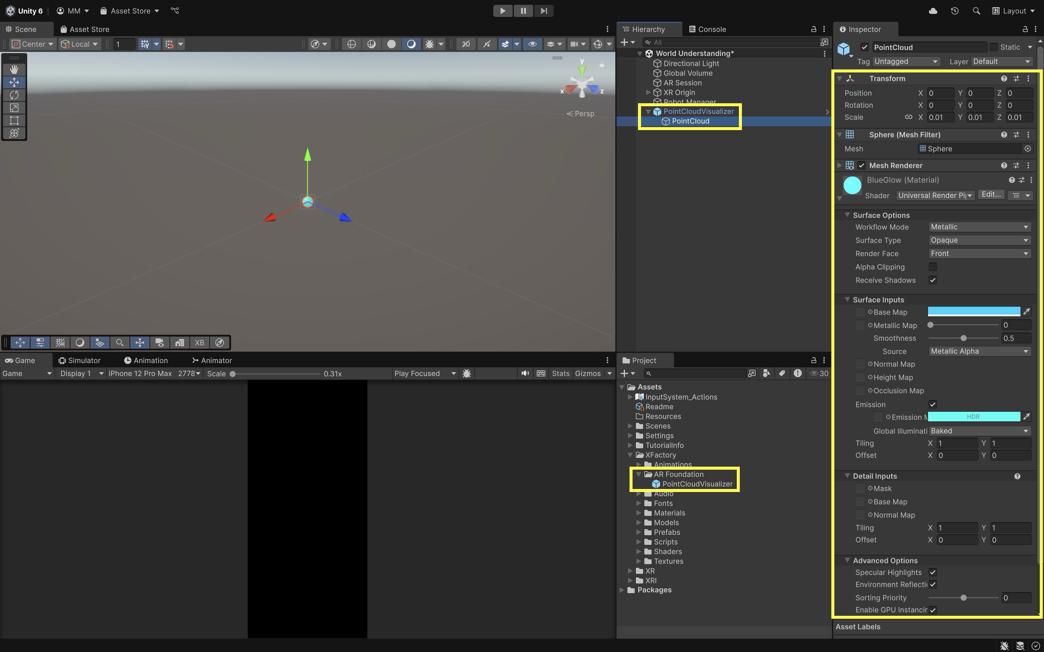
Hierarchy, right-click and chooseXR > AR Default Point Cloud. - Drag the resulting prefab into
Assets/Prefabsif you want a project copy, then remove the scene instance until the manager assigns it. - A custom point cloud visualizer requires a script that updates or pools point markers; a single sphere child does not automatically visualize every feature point.
- In
- Add
ARPointCloudManager:- Select
XR Origin. - Click
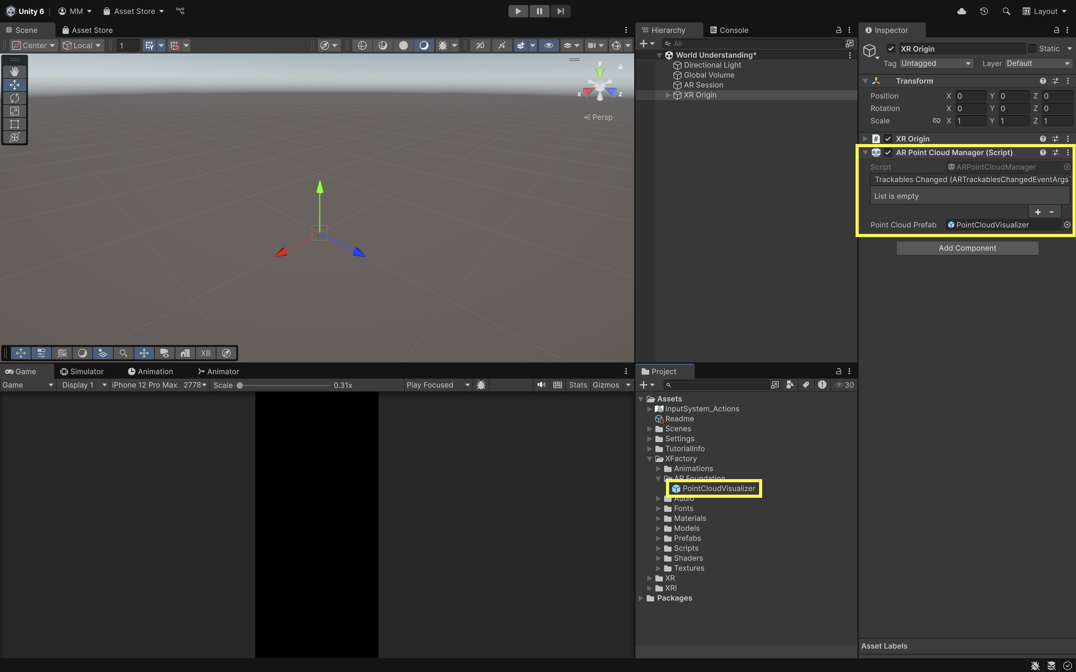
Add Component > AR Point Cloud Manager. - In the
Inspector, assign theAR Default Point Cloudprefab to thePoint Cloud Prefabfield.
- Select
- Test Point Cloud Visualization on Device:
- Deploy and run on a physical phone or tablet.
- Slowly scan the floor and nearby surfaces to accumulate feature points.
- Use the visualization to judge whether the environment has enough texture and lighting for stable tracking.
- Tap-to-place robot spawning is covered in the Planes section using
ARRaycastManager—that is the recommended placement path for this course.
For stable placement, prefer plane raycasts and anchors over averaging raw feature points. Point clouds remain valuable for assessing tracking quality under different lighting and surface conditions.
Planes

In mathematics, a plane is an infinite, flat, two-dimensional surface. In AR, we model real-world flat areas—such as floors, tables, and walls—as finite planar surfaces that can host or constrain virtual content. Plane detection is essential because it gives structure and meaning to the raw 3D points captured by the AR system, allowing virtual objects to behave as if they exist in the user’s physical space. For example, a virtual quadruped robot should recognize and move only across horizontal planes (the floor) and avoid vertical planes (walls, furniture) to navigate safely—mirroring how spatial awareness guides real-world motion. Plane detection thus bridges low-level spatial mapping with high-level semantic understanding and interaction. Key advantages of plane detection include:
- Anchor Stability: Attaching anchors to planes keeps virtual content fixed in place, preventing objects from drifting or sliding as the device moves, ensuring a stable and believable AR experience.
- User Intuition: Interacting with familiar, recognizable surfaces—like tapping a tabletop to place an object—feels natural and enhances usability.
- Occlusion and Physics: Understanding where real surfaces exist enables realistic occlusion and physical responses, such as a ball rolling off a table edge or a robot stopping before a wall.
Use Cases
AR systems extract structured surfaces (planes) from raw spatial data (point clouds) through a multi-stage process. The early stages build the point cloud, while later stages interpret that data to produce planes and their boundaries.
Point Cloud Generation
- Feature Extraction: The AR runtime scans each camera frame for distinct, high-contrast “feature points” such as edges, corners, or textured regions that are easy to track over time. These points form the foundation of the point cloud and are essential for reliable spatial mapping—poor lighting, low texture, or motion blur can reduce the number of usable features.
- Depth and Motion Estimation: By observing how these feature points move between frames, the AR system estimates camera motion and reconstructs a 3D point cloud of the surrounding environment. This data allows the system to maintain accurate tracking and spatial awareness, ensuring virtual objects stay locked in place as the user moves.
Plane Detection and Representation
- Plane Fitting: From the accumulated point cloud, clustering and statistical methods (such as RANSAC) identify groups of coplanar points that correspond to flat surfaces like floors, walls, and tables. This converts raw point data into meaningful, usable geometry.
- Boundary Extraction: Once a plane is detected, the system projects all inlier points onto it and computes a 2D polygon boundary representing its shape and extent. These boundaries define where virtual objects can be placed or where navigation paths are valid.
Optional Plane Features
- Arbitrary Alignment: Detects sloped or angled planes beyond horizontal or vertical surfaces.
- Classification: Semantic labels such as floor, wall, ceiling, table, or seat—provider-dependent and not available on every device.
- Boundary Vertices: Provides the polygon coordinates of each plane for accurate visual rendering, physics, and collision handling.
Plane alignment is commonly available; semantic classification is provider-dependent. For the robot tutorial, use
PlaneAlignment.HorizontalUpas the spawn surface and treatPlaneAlignment.Verticalas wall-like obstacle behavior. When classification is supported, you can add optional filters such asPlaneClassification.Floor.
Lifecycle and State
Each plane also carries a trackingState (Tracking, Limited, None) to indicate confidence in its position and orientation (pose). It is essential to check for Tracking before placing or interacting with critical AR content—otherwise, virtual objects may jitter, drift, or appear misaligned. Tracking state changes often occur due to user movement, lighting shifts, or partial occlusion of the surface. AR planes typically pass through three lifecycle phases:
- Added: A new flat area is discovered and reported by the AR subsystem. This is the first time the plane is recognized, often with minimal size and shape information—ideal for triggering initial placement prompts.
- Updated: The plane’s boundaries, alignment, and pose are refined as more of the surface is observed from different angles. Updates can expand plane coverage, improve polygon accuracy, and merge overlapping detections into a single surface.
- Removed: The subsystem determines that the plane is no longer valid—perhaps because it was merged with another plane, the surface is no longer visible, or tracking confidence dropped to zero. Removal events should trigger cleanup of any dependent virtual content or logic tied to that surface.
Review this Unity documentation to learn more about the AR Plane Manager component and AR Plane component.
Implementing AR Planes
Let’s visualize horizontal and vertical AR planes and spawn and control the quadruped robot (Spot Animated) so it walks on horizontal floor planes and stops if it collides with walls. This illustrates how plane alignment and plane boundaries can control robot behavior in mobile AR.
- Create a
Robot Managerobject:- Create an empty GameObject named
Robot Managerin the scene. You will attach spawner scripts here in later steps.
- Create an empty GameObject named
- Create a Plane Visualizer Prefab:
- In the
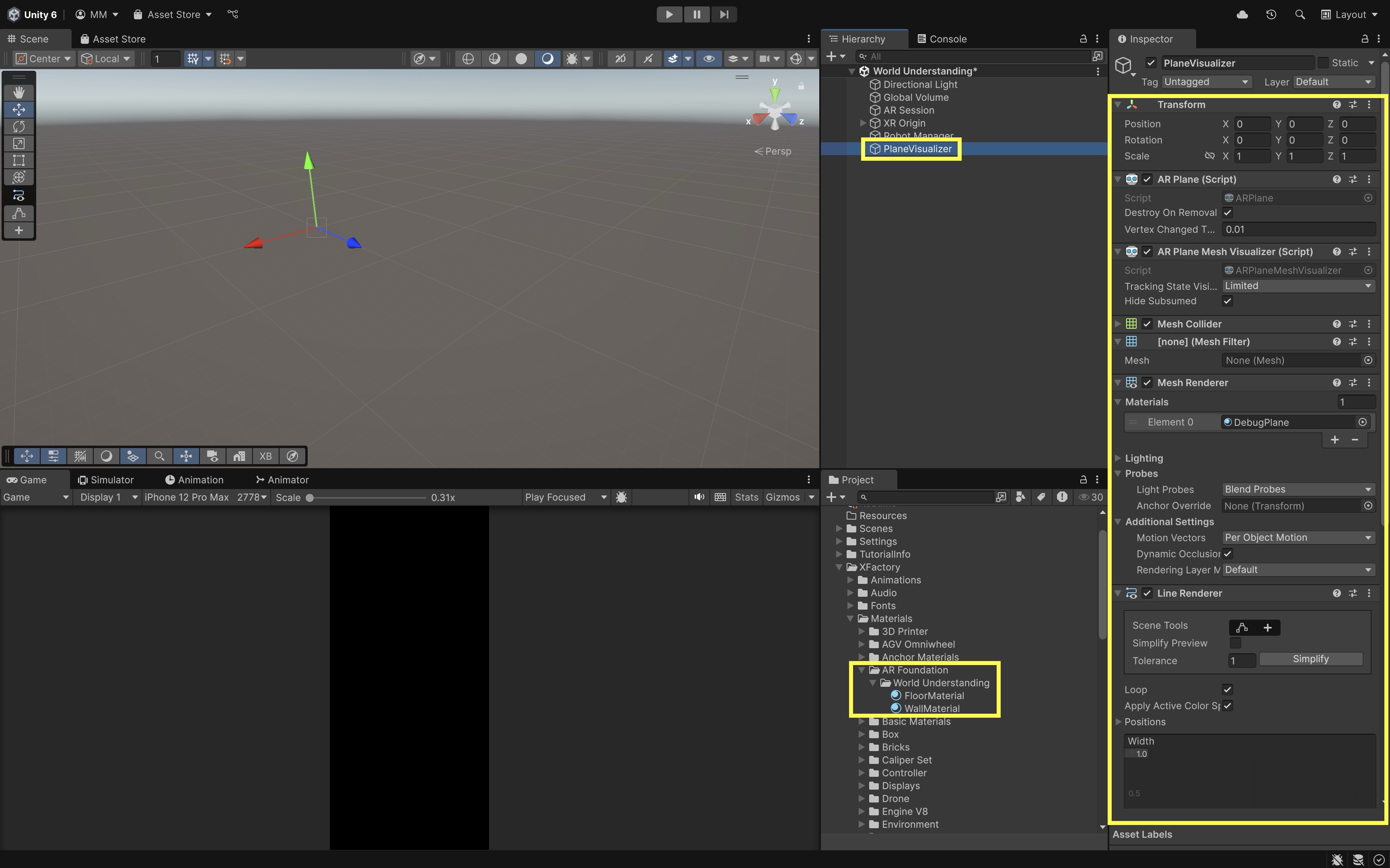
Hierarchy, right-click and chooseXR > AR Default Plane. - Rename it to
PlaneVisualizer. - Inspect its components:
ARPlanetracks surface data,ARPlaneMeshVisualizerrenders the mesh geometry, andMeshRendererapplies the material. - Create two new materials in
Assets/Materials. SetFloorMaterialto light blue with ~50% alpha (A=120) andWallMaterialto Transparent red with ~50% alpha.
- In the
- Create a Plane Material Setter Script:
- Create a script named
PlaneMaterialSetter.cs. - Attach it to the plane prefab.
using UnityEngine; using UnityEngine.XR.ARFoundation; using UnityEngine.XR.ARSubsystems; [RequireComponent(typeof(ARPlane))] public class PlaneMaterialSetter : MonoBehaviour { [SerializeField] private Material horizontalMaterial; [SerializeField] private Material verticalMaterial; private ARPlane plane; private MeshRenderer meshRenderer; void Awake() { plane = GetComponent<ARPlane>(); meshRenderer = GetComponent<MeshRenderer>(); } void OnEnable() { if (plane != null) plane.boundaryChanged += OnPlaneChanged; UpdateMaterial(); } void OnDisable() { if (plane != null) plane.boundaryChanged -= OnPlaneChanged; } void OnPlaneChanged(ARPlaneBoundaryChangedEventArgs args) => UpdateMaterial(); void UpdateMaterial() { if (meshRenderer == null || plane == null) return; Material chosen = horizontalMaterial; switch (plane.alignment) { case PlaneAlignment.HorizontalUp: case PlaneAlignment.HorizontalDown: chosen = horizontalMaterial; break; case PlaneAlignment.Vertical: chosen = verticalMaterial; break; } if (chosen != null) meshRenderer.sharedMaterial = chosen; } } - Create a script named
- Configure the Script:
- In the
Inspector, dragFloorMaterialtoHorizontal MaterialandWallMaterialtoVertical Material. - Drag the
PlaneVisualizerobject intoAssets/Prefabsto save it as a prefab. You can now delete it from theHierarchy.
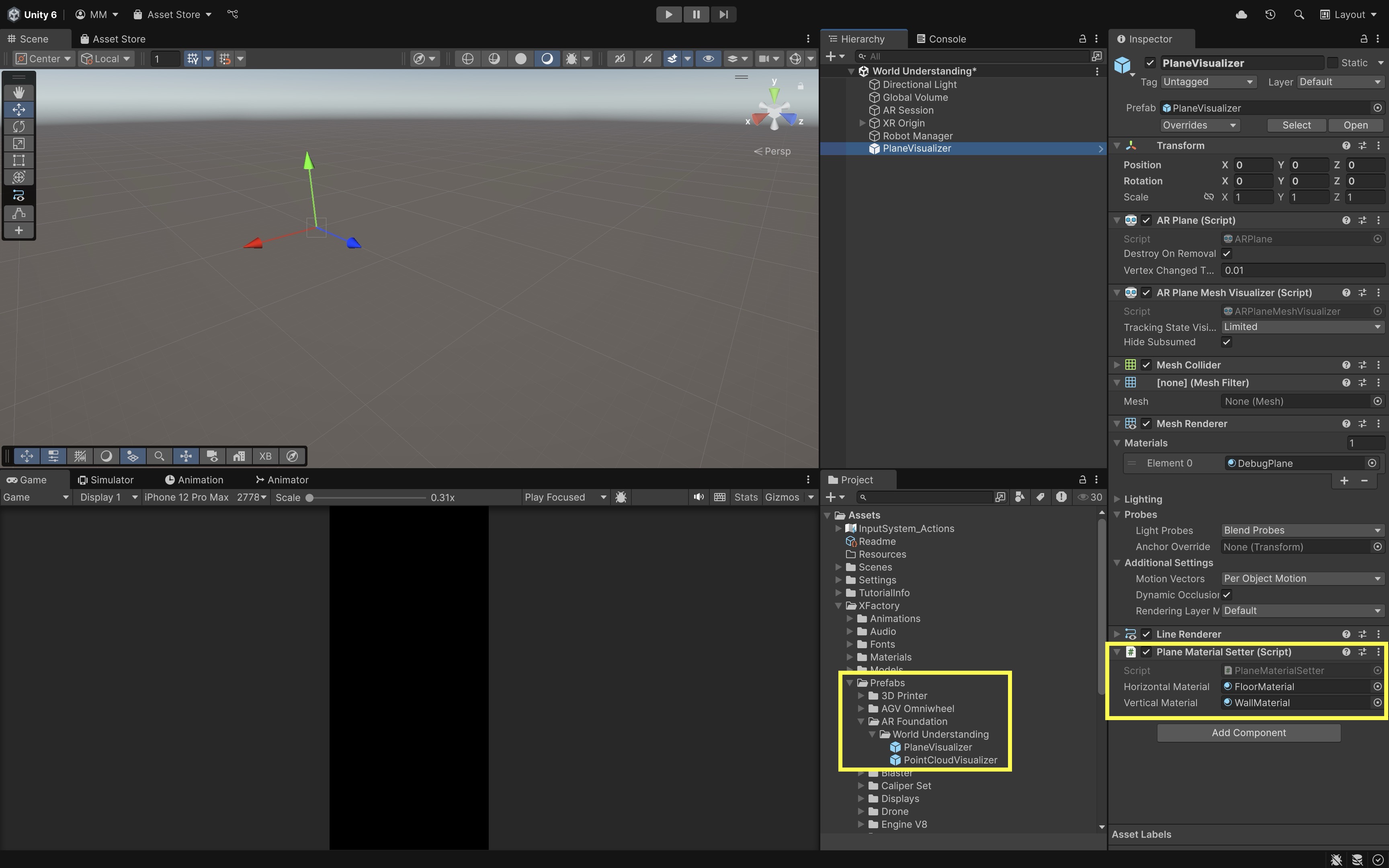
With this setup, every detected surface will be colored appropriately: blue for floor planes and red for walls—without needing multiple prefabs.
- In the
- Add AR Plane Detection:
- Select
XR Origin. - Add
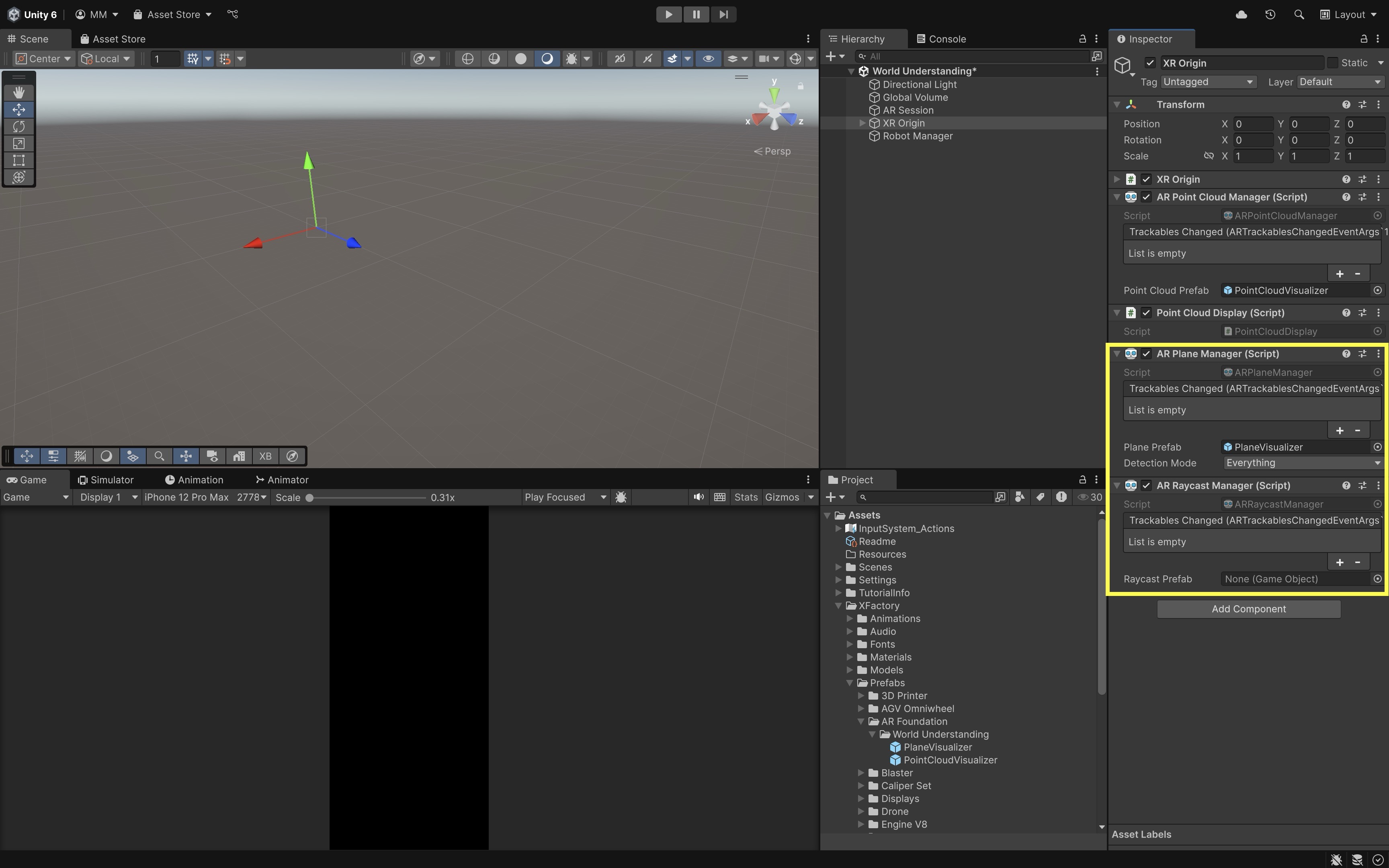
Component > AR Plane Manager. - Assign the
PlaneVisualizerprefab you just created to thePlane Prefabfield of theAR Plane Manager. - Set
Detection ModetoEverything(horizontal and vertical). - Still on
XR Origin, addARRaycastManager. Leave theRaycast Prefabfield empty. TheARRaycastManagerallows you to cast rays from the screen into the AR scene to detect tracked planes. - It might be a good idea to disable or remove the
ARPointCloudManagernow to reduce clutter. Plane meshes provide more structured visual feedback for placement and obstacle logic.
- Select
- Spawn Robot on Floor Using Plane Raycasts:
- Create a script
ClassifiedRobotSpawner.csand attach it toRobot Manager. - This script uses Input System enhanced touch and spawns the robot only on
HorizontalUpplanes.
using System.Collections.Generic; using UnityEngine; using UnityEngine.InputSystem.EnhancedTouch; using UnityEngine.XR.ARFoundation; using UnityEngine.XR.ARSubsystems; using Touch = UnityEngine.InputSystem.EnhancedTouch.Touch; public class ClassifiedRobotSpawner : MonoBehaviour { [SerializeField] private GameObject robotPrefab; [SerializeField] private ARRaycastManager raycastManager; [SerializeField] private ARPlaneManager planeManager; private GameObject spawnedRobot; private readonly List<ARRaycastHit> hits = new List<ARRaycastHit>(); void OnEnable() => EnhancedTouchSupport.Enable(); void OnDisable() => EnhancedTouchSupport.Disable(); void Update() { if (spawnedRobot != null || Touch.activeTouches.Count == 0) return; var touch = Touch.activeTouches[0]; if (touch.phase != UnityEngine.InputSystem.TouchPhase.Began) return; if (robotPrefab == null || raycastManager == null || planeManager == null) { Debug.LogWarning("ClassifiedRobotSpawner: missing references."); return; } if (!raycastManager.Raycast( touch.screenPosition, hits, TrackableType.PlaneWithinPolygon)) return; var hit = hits[0]; var plane = planeManager.GetPlane(hit.trackableId); if (plane == null) return; if (plane.alignment != PlaneAlignment.HorizontalUp) { Debug.Log( $"Rejected plane — alignment was {plane.alignment}, expected HorizontalUp." ); return; } spawnedRobot = Instantiate( robotPrefab, hit.pose.position, Quaternion.identity ); Debug.Log($"Robot spawned at: {hit.pose.position}"); } } - Create a script
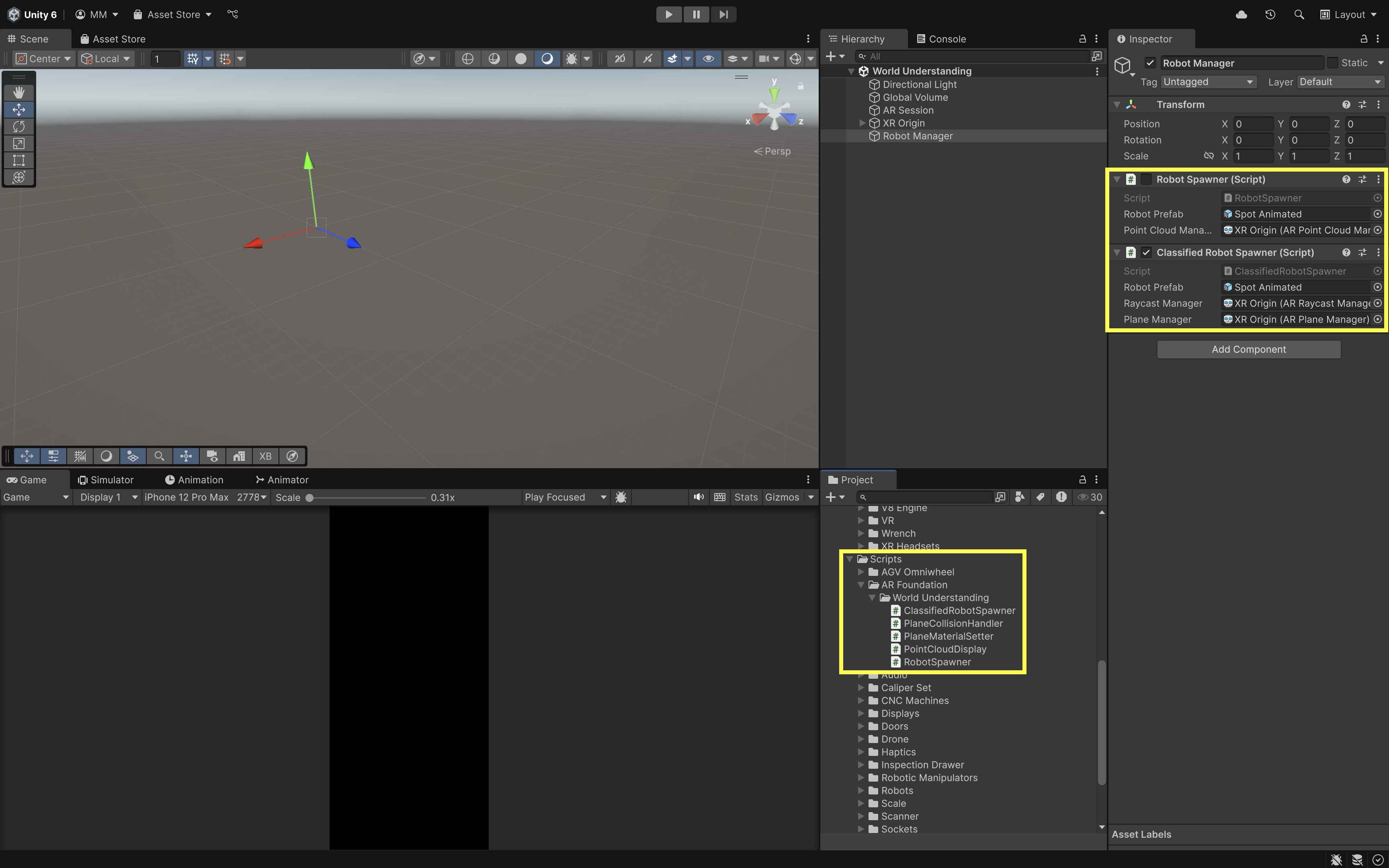
- Configure the Script:
- Drag
Spot AnimatedintoRobot Prefab. - Drag
XR Origininto bothRaycast ManagerandPlane Manager. - Use the course-standard Input System Package (New) player setting. Do not switch to
Bothunless a specific dependency requires compatibility mode.
- Drag
- Create a Script to Stop the Robot on Wall Collision:
- Create a new script called
StopOnWallCollision.cs. - Attach it to the
Spot Animatedrobot prefab. This script stops walking logic when the robot detects a nearby vertical plane ahead. - World-space AR raycasts are provider-dependent. If unsupported or unreliable, use physics colliders on plane visualizers or a simpler proximity check instead.
 using System.Collections.Generic;
 using UnityEngine;
 using UnityEngine.XR.ARFoundation;
 using UnityEngine.XR.ARSubsystems;

 public class StopOnWallCollision : MonoBehaviour
 {
     [SerializeField] private ARRaycastManager raycastManager;
     [SerializeField] private float stopDistance = 0.6f;
     [SerializeField] private float rayYOffset = 0.1f;

     private Animator anim;
     private SpotWalker walker;
     private static readonly List<ARRaycastHit> hits = new List<ARRaycastHit>(4);

     void Awake()
     {
         anim = GetComponent<Animator>();
         walker = GetComponent<SpotWalker>();
         if (raycastManager == null)
             raycastManager = FindFirstObjectByType<ARRaycastManager>();
         if (raycastManager == null)
             Debug.LogWarning("StopOnWallCollision: ARRaycastManager not assigned.");
     }

     void Update()
     {
         if (walker == null || !walker.enabled || raycastManager == null)
             return;

         Vector3 origin = transform.position + Vector3.up * rayYOffset;
         Vector3 dir = transform.forward;

         if (!raycastManager.Raycast(
                 new Ray(origin, dir),
                 hits,
                 TrackableType.PlaneWithinPolygon))
             return;

         var hit = hits[0];
         if (hit.trackable is ARPlane plane &&
             plane.alignment == PlaneAlignment.Vertical &&
             hit.distance <= stopDistance)
         {
             // Beginner simplification: disabling Animator freezes pose.
             // Prefer a dedicated stop method on SpotWalker when available.
             walker.enabled = false;
             if (anim) anim.enabled = false;
             Debug.Log(
                 "Stopped: vertical plane ahead. Visualization/training behavior only—not validated navigation."
             );
         }
     }
 }
This is a visualization/training behavior, not a validated robot navigation or safety system. Casting multiple forward rays can improve wall detection when planes are partial or angled.
- Create a new script called
- Test the Behavior:
- Deploy your AR app to a device.
- Walk around to scan your environment.
- Tap to spawn the robot on the floor.
- Place or walk it toward a detected vertical plane (e.g., wall).
- When the robot touches the wall, it should stop moving and stop animating.
After placement, you can hide plane visuals to reduce clutter. Disable plane detection only if the app no longer needs plane updates—for example, if the robot still uses planes for ongoing obstacle logic, keep detection enabled.
Meshing
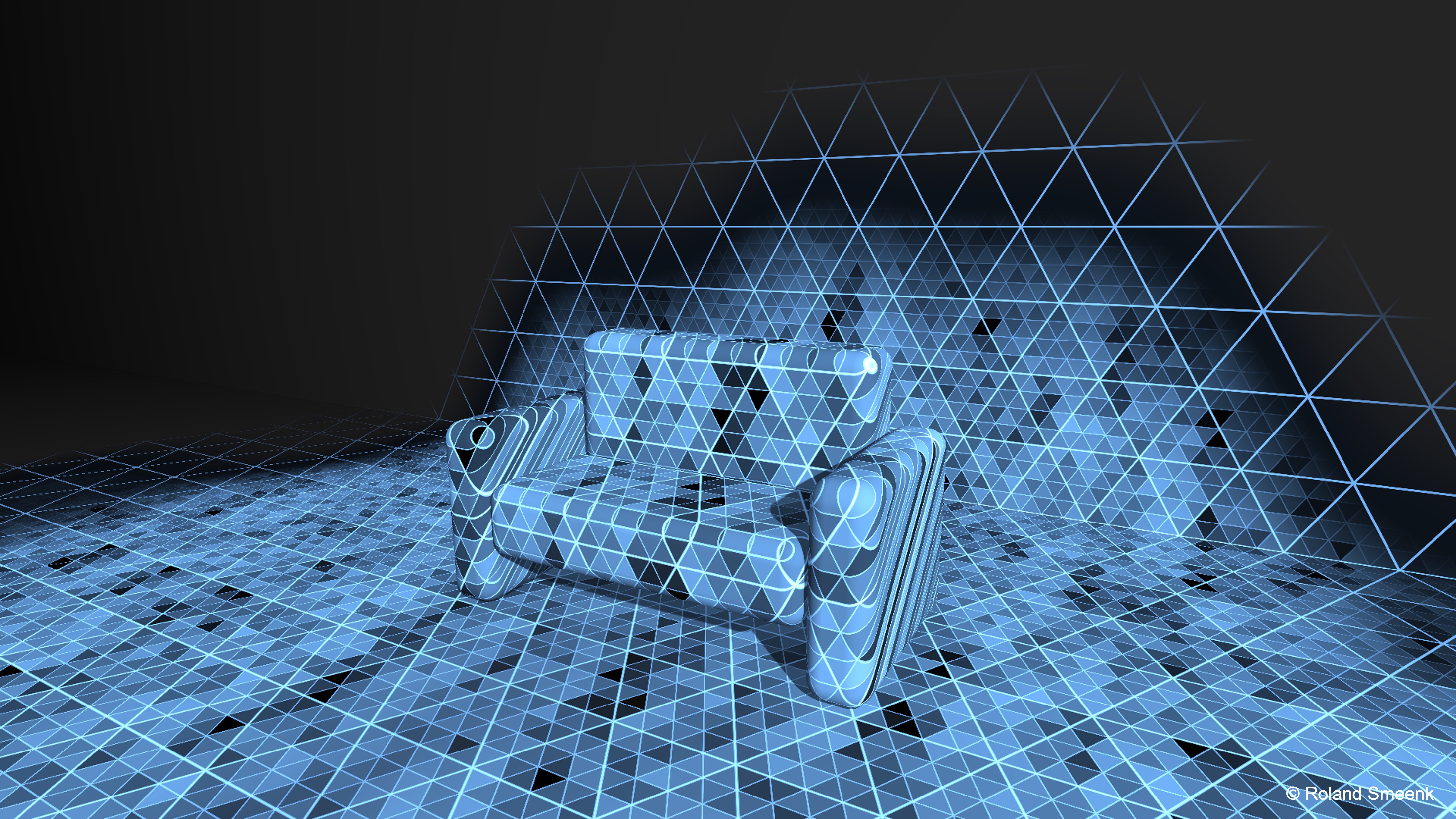
Meshing in AR is the real-time construction of a polygonal surface model from depth data captured by a device’s sensors (e.g., LiDAR, depth camera, structured light). Rather than just detecting flat planes, meshing samples depth at many points to create a dense point cloud, triangulates those points into interconnected triangles, forming a continuous surface mesh, and outputs a Unity Mesh object you can render, collide against, or use for occlusion. For example, as the virtual quadruped robot moves around a cluttered office or lab, the ARMeshManager can build mesh chunks for chairs, desks, and boxes on supported devices. The robot’s path-planning script can check these chunks and stop when an obstacle mesh collides with it—similar to a Roomba avoiding furniture legs, but this remains a visualization/training behavior, not validated navigation. Key benefits of meshing in AR include:
-
Precision: Meshing captures curved and irregular surfaces, not just planes. This makes it possible to represent stairs, uneven terrain, and organic shapes with high fidelity, enabling realistic navigation, placement, and collision for virtual content.
-
Interaction: Meshes let virtual objects rest naturally on real-world topology (e.g., a ball rolling down a real staircase). This improves immersion by ensuring physics interactions match the actual environment’s contours, whether for entertainment, training, or robotics applications.
-
Occlusion and Anchoring: Meshes can hide virtual content behind real geometry or provide robust spatial anchors on complex shapes. This allows, for example, a holographic model to disappear correctly when it moves behind a real desk, or for a spatial marker to remain locked onto an irregular object rather than a flat plane.
Meshing is not universally available on mobile AR devices. It depends on device sensors and provider support. Treat meshing examples as advanced and test on supported hardware. It is platform-dependent: ARKit, ARCore, and headset providers each have different meshing pipelines, sensor requirements, and performance trade-offs. On LiDAR-enabled devices, updates can be nearly real-time, while camera-based depth reconstruction may be slower and less detailed. Always consult target device documentation for mesh density, refresh rates, and occlusion support.
Features
The ARMeshManager component orchestrates platform meshing and exposes tunable properties depending on provider support:
- Mesh Prefab: Every scan volume generates discrete mesh “chunks,” each instantiated from your
Mesh Prefab. That prefab must include aMeshFiltercomponent (required) that holds the generatedMeshdata, aMeshRenderer+Material(optional) to visualize the scanned surface, and aMeshCollider(optional) to enable physical interactions against the real-world mesh. Use mesh colliders only when needed—they can be costly on mobile devices. - Density and vertex attributes: Depending on provider support, the manager may expose settings such as density, normals, tangents, texture coordinates, colors, and queue size. Higher density improves fidelity but increases CPU/GPU cost; disable vertex attributes you do not use.
- Concurrent Queue Size: To keep the main thread smooth,
ARMeshManageroffloads converting raw sensor mesh data to UnityMeshobjects and generating collision meshes when aMeshCollideris present. Larger queues can reduce visible update latency but may increase memory use.
Meshing Best Practices
- Optimization: Lower density and disable unused attributes in performance-sensitive apps. This reduces CPU/GPU workload, improves frame rates, and helps maintain tracking stability—especially on mobile devices where thermal throttling can occur during long sessions.
- Chunk Size: Some platforms let you configure how large each mesh section is—smaller chunks mean faster updates but more overhead. Smaller chunks are ideal for dynamic environments or robotics navigation where rapid mesh changes matter, while larger chunks are better for static scenes to reduce draw calls and memory use.
- Material Choice: Wireframe or semi-transparent shaders help debug mesh coverage. These visualization techniques make it easier to spot gaps, overlapping geometry, or poorly scanned areas during development, even if the mesh will be hidden in the final application.
- Persistence: For mapping applications, consider serializing meshes to disk and re-loading them in later sessions. Persistent meshes allow for large-scale mapping over time, enabling use cases like multi-session scanning, AR indoor navigation, or collaborative construction planning.
Implementing AR Meshes
Now, let’s extend the previous quadruped robot navigation example by enabling AR meshing, visualizing scanned surfaces in real time, and stopping the robot when it collides with mesh-reconstructed objects (e.g., furniture, boxes).
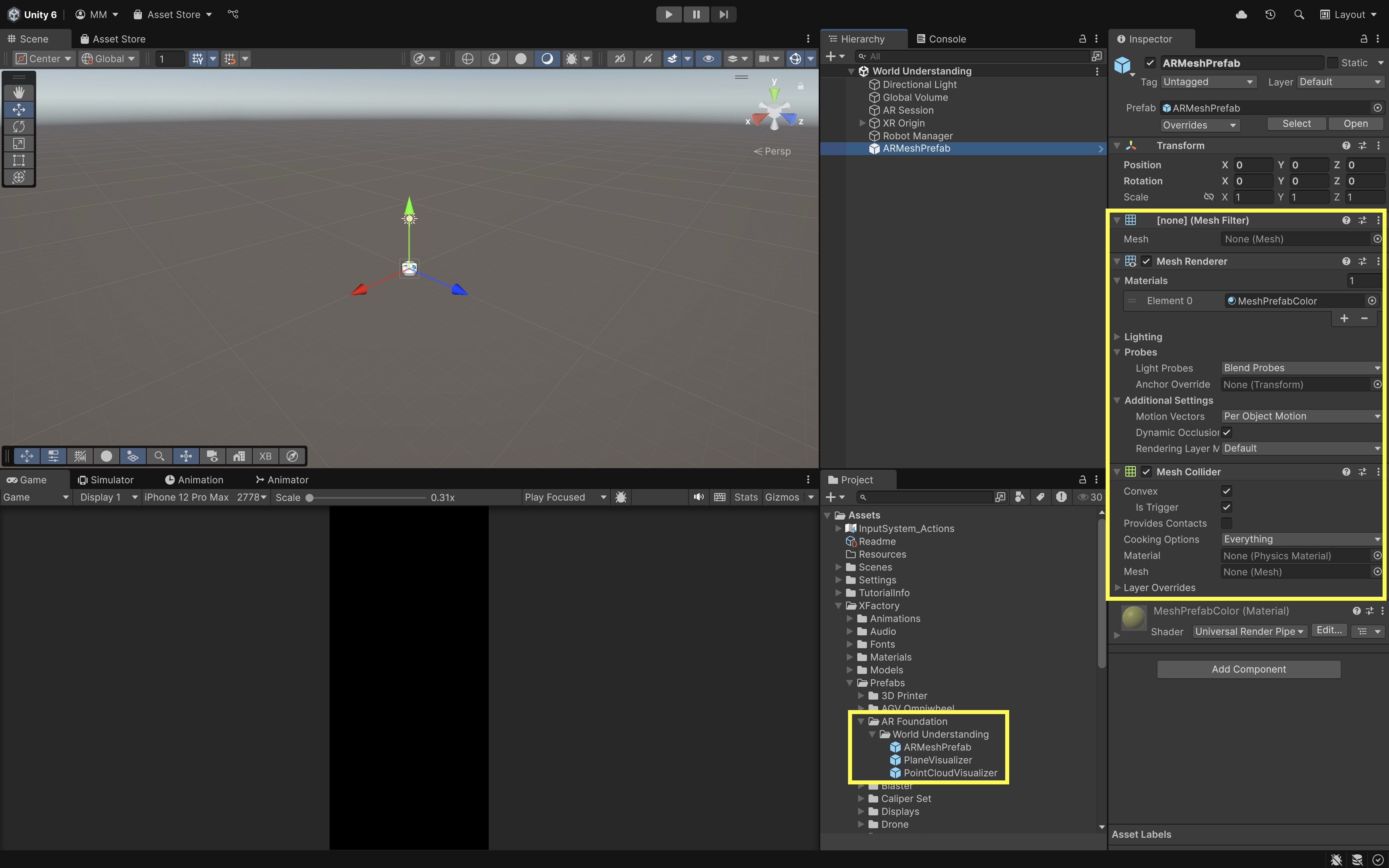
- Create a Mesh Prefab:
- In the
Hierarchy, right-click and selectCreate Empty. Name itARMeshPrefab. - Select
ARMeshPrefab. - Add a
MeshFiltercomponent. Leave theMeshfield empty.ARMeshManagerautomatically assigns the mesh data at runtime to theMeshFilterof each mesh chunk it generates. - Add a
MeshRenderercomponent for visualization (optional). Assign a semi-transparent material. - Add a
MeshCollidercomponent only if you need physics interaction. Use mesh colliders only when needed—they can be costly on mobile devices. If using trigger-based detection, test whether your mesh collider setup requiresConvexfor the target platform and keep mesh density low.Convexmay simplify complex mesh chunks and is a performance/compatibility choice, not a universal best setting. - Drag
ARMeshPrefabinto yourProjectwindow to save it as a prefab. Remove it from theHierarchy. This prefab will be instantiated dynamically for each mesh “chunk” generated by the device in real time.
- In the
- Add
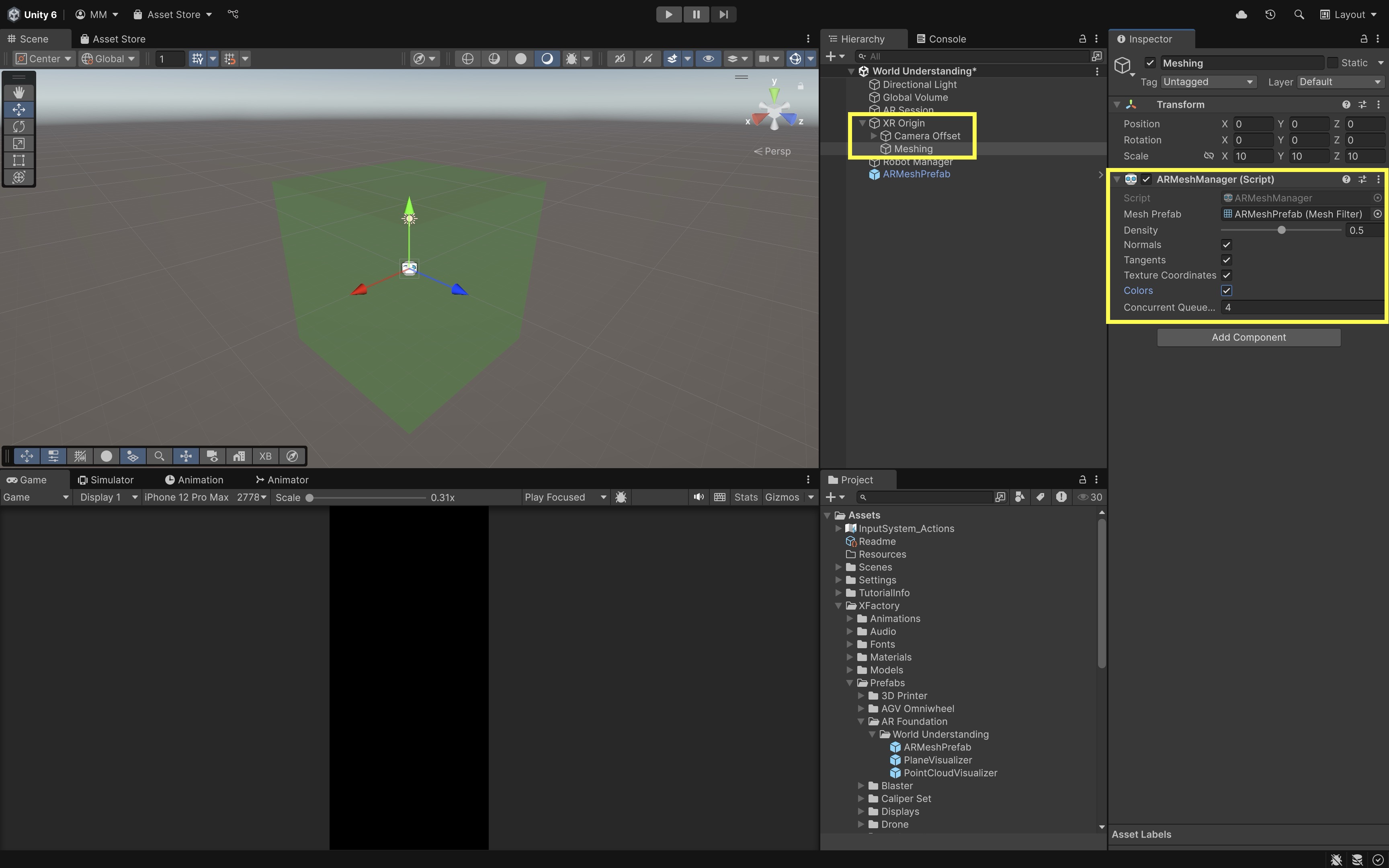
ARMeshManagerto Your Scene:- Select your
XR Origin, right-click and create an empty GameObject. Name itMeshing. - Select
Meshing, then clickAdd Component > ARMeshManager. - Go to the
Inspector. - Assign your
ARMeshPrefabto theMesh Prefabfield. - Adjust density and vertex attributes if your provider exposes them—start conservative on mobile devices.
- Leave queue size at default unless you need faster mesh updates and can afford the memory cost.
- (Optional) Toggle mesh renderer visibility at runtime to reduce clutter during robot operation.
- Select your
- Stop the Robot When It Hits a Mesh:
- Create a new script called
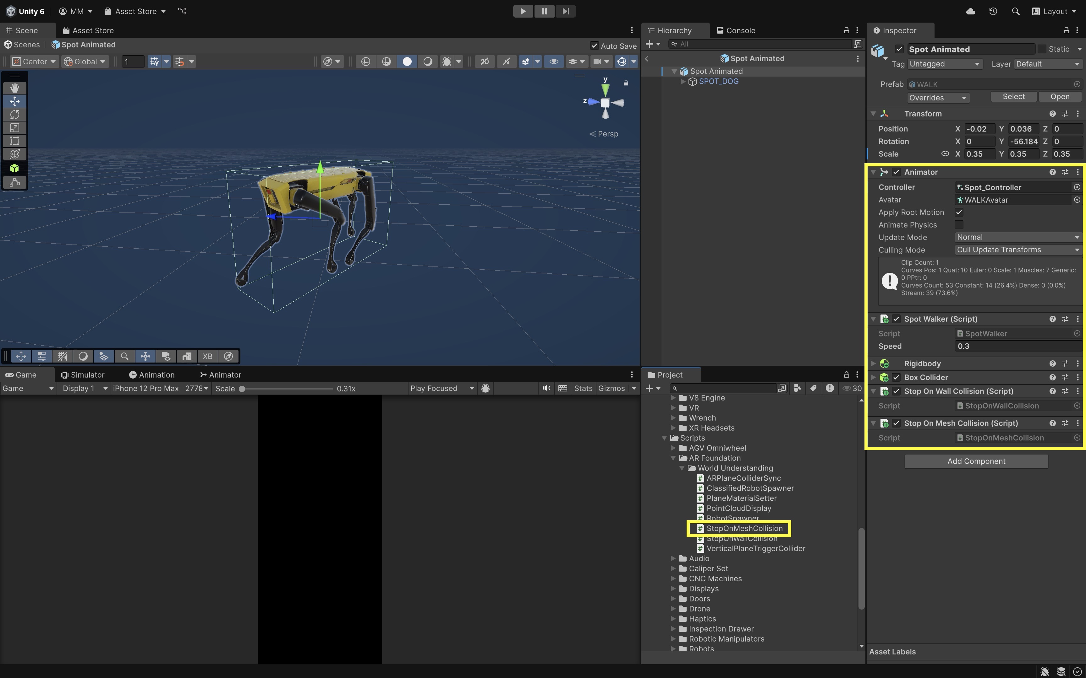
StopOnMeshCollision.cs. - Attach it to your robot (i.e.,
Spot Animatedprefab). This script stops the robot when it bumps into an AR mesh chunk representing a real-world obstacle—such as a scanned chair, box, or wall—while ignoring mesh surfaces near the floor. - Physics events with generated AR meshes can vary by provider and collider setup. Test trigger/collision behavior on device.
using UnityEngine; public class StopOnMeshCollision : MonoBehaviour { [SerializeField] private float minCollisionHeight = 0.1f; private Animator animator; private SpotWalker walker; private Collider robotCollider; void Awake() { animator = GetComponent<Animator>(); walker = GetComponent<SpotWalker>(); robotCollider = GetComponent<Collider>(); if (robotCollider == null) Debug.LogWarning("StopOnMeshCollision: no Collider on robot."); } void OnTriggerEnter(Collider other) { if (robotCollider == null) return; if (!other.TryGetComponent<MeshCollider>(out _)) return; Vector3 contactPoint = other.ClosestPoint(transform.position); float robotBaseHeight = robotCollider.bounds.min.y; if (contactPoint.y - robotBaseHeight < minCollisionHeight) { Debug.Log("Mesh contact below robot — ignoring."); return; } Debug.Log("Robot collided with mesh above floor — stopping."); if (walker) walker.enabled = false; else if (animator) animator.enabled = false; } } - Create a new script called
- Configure the Script:
- Ensure the
Spot Animatedrobot has aBoxColliderorCapsuleCollider, plus aRigidbodywithIs KinematicandUse Gravitydisabled. - For trigger events, the robot collider and generated mesh collider setup must support triggers on your target platform.
- Keep
StopOnWallCollision.csif you still want the robot to stop at both vertical planes and scanned mesh obstacles. - This is a visualization/training behavior, not validated robot navigation or safety logic.
- Ensure the
- Test the Behavior:
- Deploy the app.
- Tap to spawn the robot on a horizontal plane.
- As the robot walks,
ARMeshManagercontinuously generates 3D surface meshes. - If the robot touches one of those mesh chunks (e.g., a chair), it immediately stops.
Occlusion
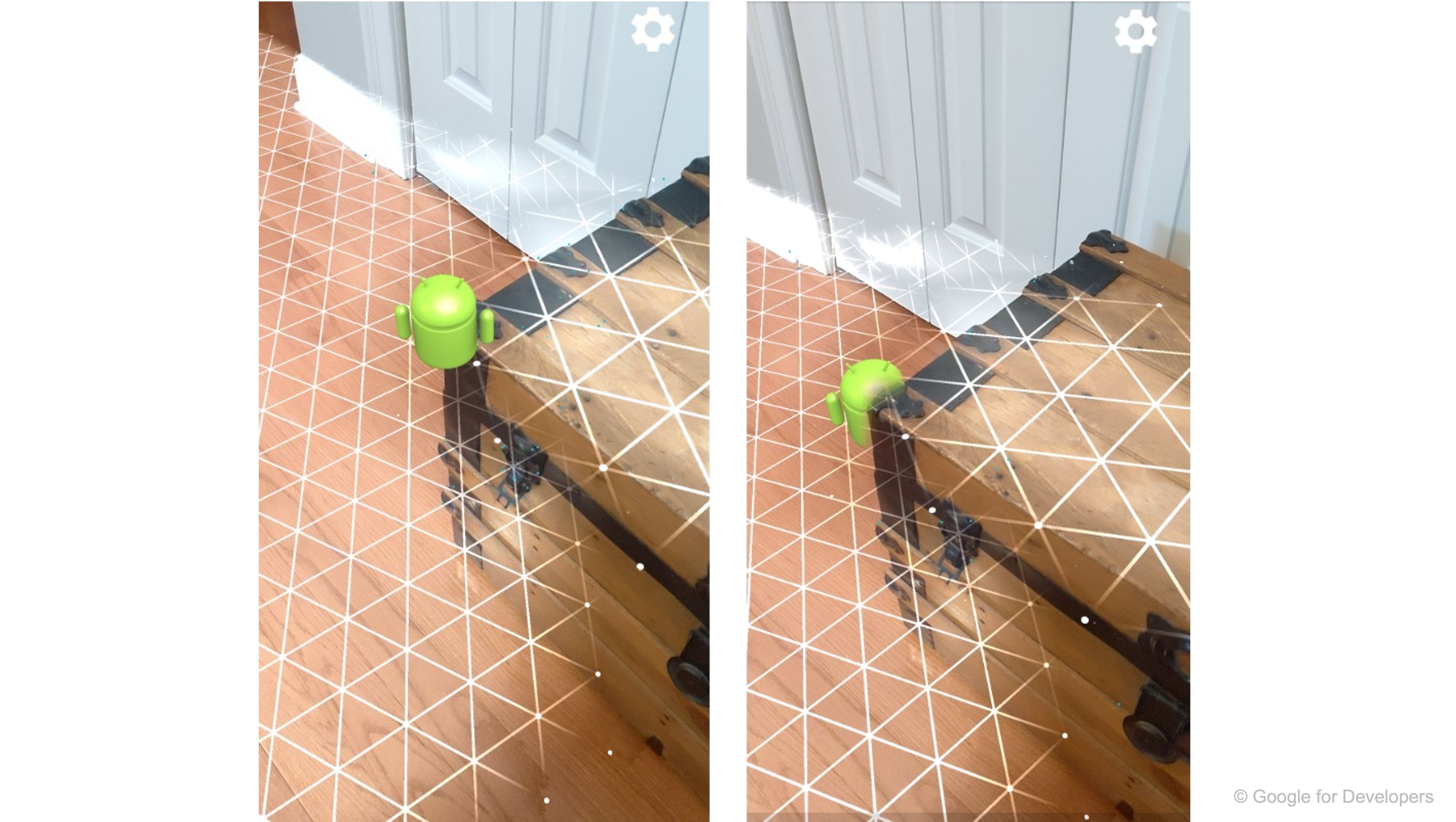
Occlusion ensures virtual content in an AR scene is correctly hidden behind real-world objects based on depth. By comparing the per-pixel distance of real surfaces (from a depth image) against the virtual geometry’s depth, the renderer discards pixels of virtual objects that lie “behind” real ones—making digital elements appear truly embedded in the environment. For example, as the quadruped robot patrols the room, it vanishes when it walks behind an object (e.g., furniture) and reappears when it emerges—exactly how a physical robot would disappear from view. This seamless hide-and-reveal dramatically increases the believability of the robot’s presence. Key benefits of occlusion in AR include:
- Immersion and Believability: Virtual objects that pass behind chairs, people, or walls reinforce depth cues, making experiences more convincing. This mirrors real-world visual behavior, helping users accept virtual elements as part of their actual surroundings instead of floating overlays detached from reality.
- Visual Comfort: Incorrect layering (“AR always on top”) breaks expectations and can cause eye strain or motion sickness over prolonged use. Proper occlusion aligns virtual depth with real-world depth, reducing cognitive dissonance and making spatial transitions—like an object emerging from behind furniture—feel natural.
- Depth Perception Integrity: Without occlusion, the robot would float in front of the coffee table even when logically behind it, breaking depth perception and confusing users about where the robot actually is. Maintaining accurate occlusion prevents spatial mismatches that could hinder usability in navigation, training, or safety-critical AR workflows.
- Interaction Accuracy: Occlusion ensures that interactions between virtual and real objects appear consistent, such as a virtual ball bouncing behind a couch rather than unrealistically clipping through it. This is essential in AR gaming, training, and robotics scenarios where spatial accuracy affects task success.
- Safety and Usability: In industrial or navigation-based AR, occlusion can prevent misleading overlays that might hide real hazards or misrepresent spatial layouts. For example, keeping a machinery warning label visible instead of letting virtual content obscure it supports safer operations.
Occlusion is provider- and device-dependent. Depth support can vary widely across phones, tablets, and headsets. Occlusion can fail on reflective, transparent, dark, low-texture, or fast-moving surfaces. Do not use occlusion as proof of physical collision or safe navigation—it is a rendering cue, not a validated safety system. Review this Unity documentation to learn more about the AR Occlusion Manager component.
Depth and Stencil Pipeline
Modern AR devices provide real-time depth and stencil textures to power occlusion effects. These textures allow Unity to determine whether virtual objects—like your robot—should be visible or hidden behind real-world geometry or people. Each frame, platforms like ARKit (structured light), ARCore (time-of-flight or ML), or XR Simulation (synthetic) generate:
- Environment Depth Texture: A grayscale image where each pixel encodes the distance (in meters) from the camera to the nearest surface. This texture is the backbone of environment occlusion, letting the renderer make per-pixel comparisons between virtual object depth and real-world surfaces. Developers can sample this texture in custom shaders to fine-tune occlusion thresholds or blend virtual objects with physical geometry for advanced effects like depth-aware shadows.
- Depth Confidence Texture: A per-pixel confidence score (range: 0 to 1). High confidence in well-lit, textured scenes; low in dark or flat areas. Useful for diagnosing tracking instability, this texture can also be leveraged to adapt occlusion quality dynamically—reducing visual artifacts by fading or softening occlusion in low-confidence regions instead of producing sharp, incorrect cutouts.
- Human Stencil Texture: A binary mask identifying human silhouettes in the camera view. This mask enables human occlusion, ensuring virtual objects appear behind people but still visible through gaps like arm motions or between fingers. Human stencil/depth modes are optional and provider-dependent—mainly relevant on supported mobile providers.
Toggle a debug overlay of the environment depth texture during development to visualize occlusion coverage. Areas with missing depth (e.g., shiny tables or shadows) correlate with moments when occlusion may fail. By pairing this with the depth confidence overlay, you can quickly pinpoint whether failures are due to sensor blind spots or environmental conditions.
Occlusion Pipeline
The occlusion pipeline helps you optimize occlusion accuracy and debug subtle issues in real-world conditions—critical for immersive XR engineering apps. Occlusion in Unity flows through a consistent pipeline:
- Capture: The AR platform (e.g., ARKit, ARCore) provides synchronized RGB, depth, and optionally stencil data each frame.
AROcclusionManager: In this course setup, attach it to the AR camera underXR Origin. Some templates place camera-related AR components differently—follow your active project’s AR camera setup. The component interfaces with the underlying occlusion subsystem and may expose textures such as:environmentDepthTexturedepthConfidenceTexturehumanStencilTexturehumanDepthTexture(if enabled and supported)
- Rendering: On mobile, the AR Camera Background component uses built-in shaders to merge color and depth textures and discard fragments behind real-world surfaces.
Implementing AR Occlusion
Now that the quadruped robot can navigate the environment using AR planes and meshes, let’s enhance realism by adding occlusion—making the robot visually disappear behind real-world objects using the device’s depth camera. As the robot walks behind a desk, chair, or your hand, it should visually disappear (fully or partially), just like a real object would. This creates a more immersive AR experience. Here is how to implement this behavior:
- Add AR Occlusion Manager:
- Select the
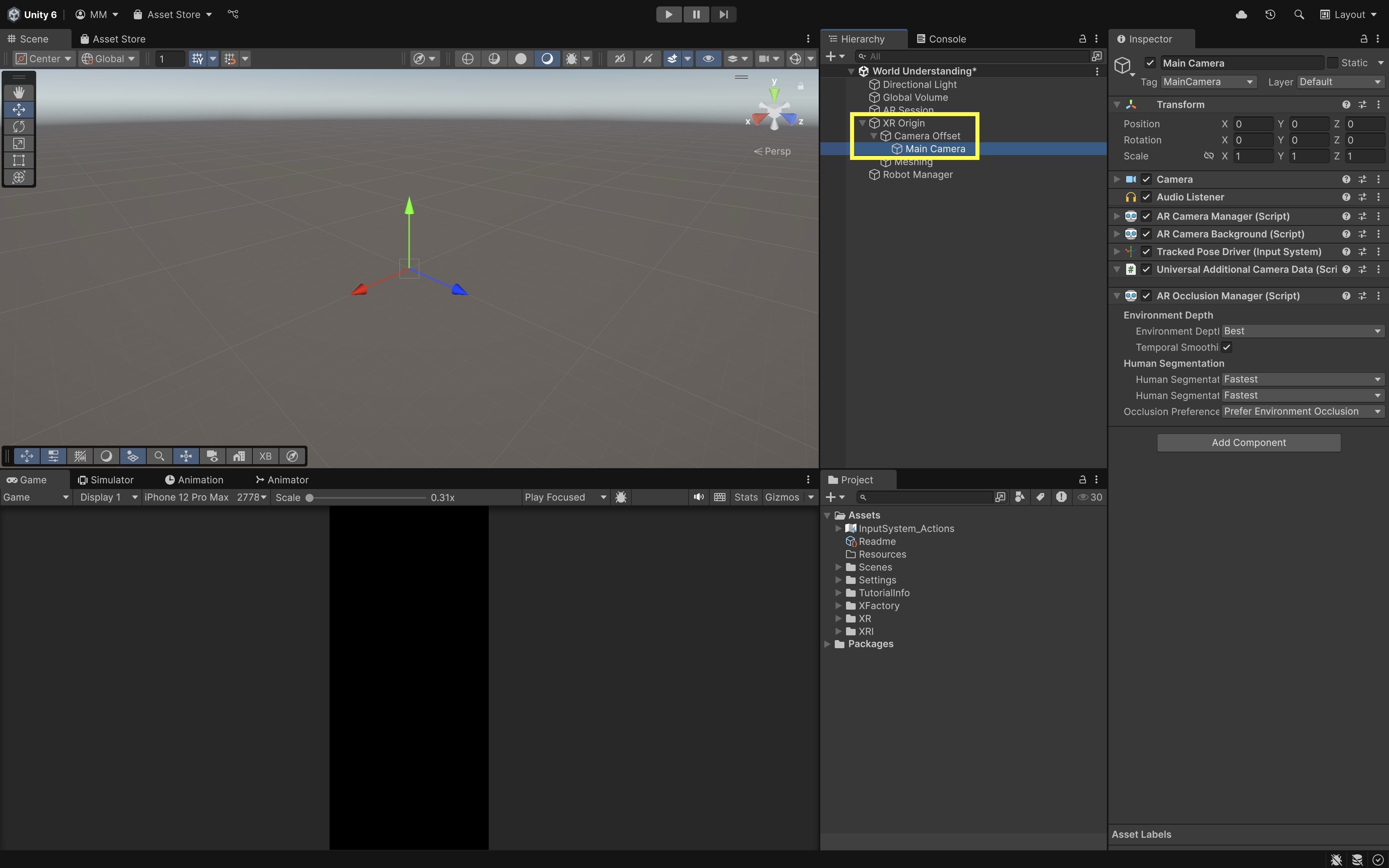
Main CameraunderXR Origin > Camera Offset. - Click
Add Component > AR Occlusion Manager. In this course setup, attachAR Occlusion Managerto the AR camera underXR Origin. Some templates or samples may place camera-related AR components differently, so follow the active project’s AR camera setup. - Go to the
Inspector. - Choose the best available environment depth mode supported by the provider. If unavailable, fall back to no environment occlusion or a simpler visual design.
- Enable
Temporal Smoothingif available to reduce visual jitter. - Human segmentation stencil/depth modes are optional and provider-dependent—enable only if your target device supports people occlusion.
- Set
Occlusion Preference Modeaccording to what your provider exposes (e.g., prefer environment occlusion when supported).
- Select the
- Hide Plane and Mesh Manager Visuals (Optional):
- Open your
Plane Prefab(e.g.,PlaneVisualizer). - Disable or remove the
MeshRendereror assign a fully transparent material to the plane mesh. - Open your
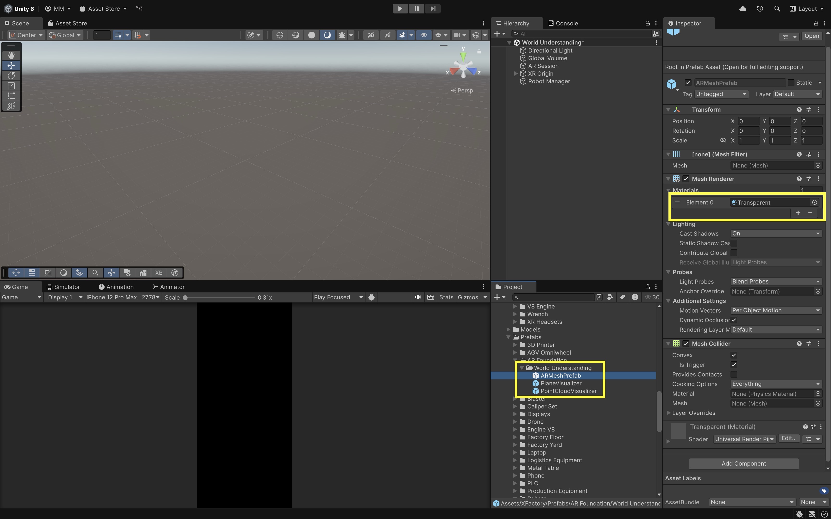
Mesh Prefab(e.g.,ARMeshPrefab). - Remove or disable the
MeshRenderercomponent, or assign a transparent or invisible material for runtime use.
- Open your
- Test the Behavior:
- Build the app to your device. Tap to spawn the robot.
- The robot disappears partially or fully as it moves behind real objects on supported hardware.
- The effect adjusts dynamically as you move the camera or real-world object.
- Compare available depth modes on your device—quality and support vary by provider.
Occlusion brings your AR engineering simulation one step closer to real-world realism. It reinforces spatial awareness and provides users with natural visual feedback as the robot navigates the physical space—but validate depth quality on each target device.
Environment Probes
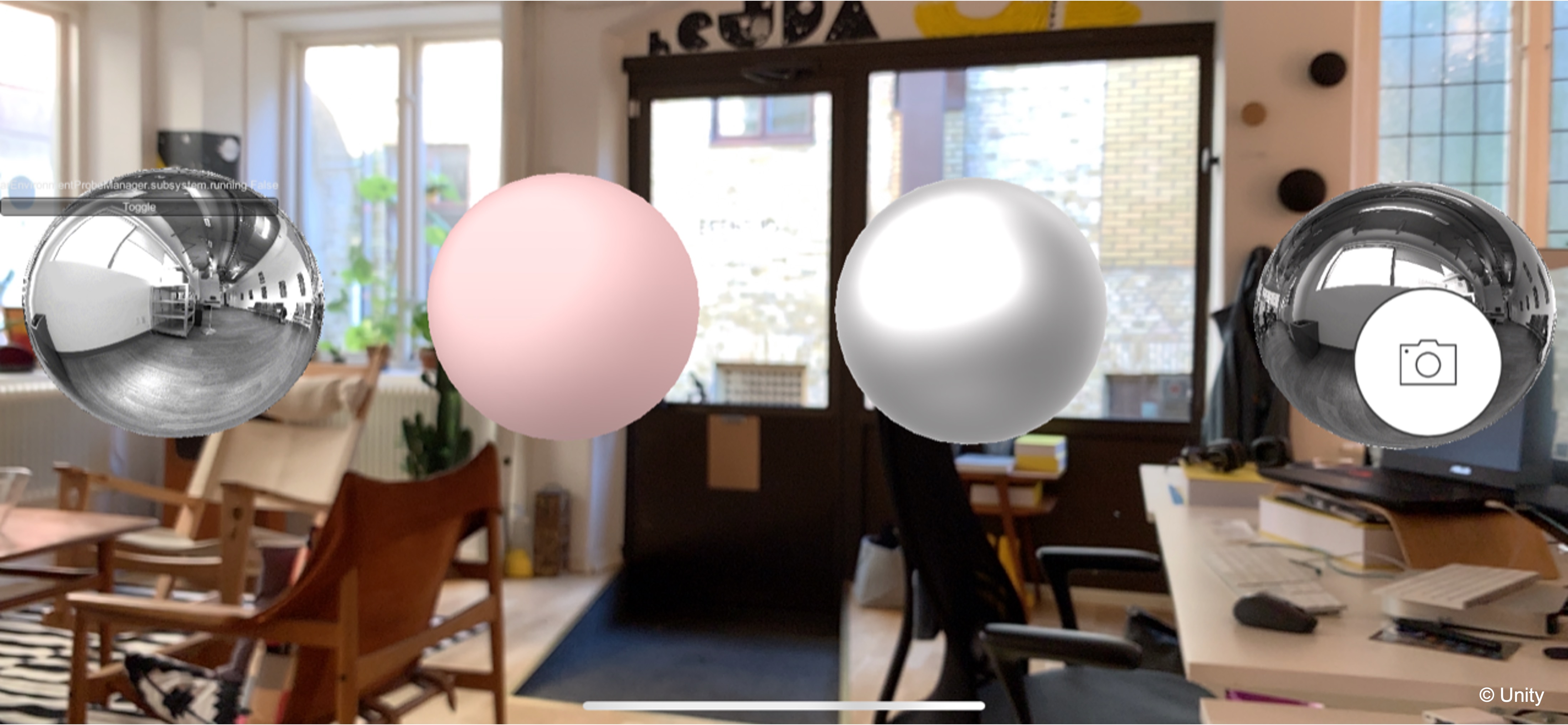
Environment probes are specialized “cameras in a box” that sample the real world at a point in space and bake that information into a cubemap—six square textures covering all directions. When you apply this cubemap to virtual materials (e.g. reflective metal or glass), those objects appear to mirror and respond to actual surroundings! For example, the quadruped robot features a polished aluminum shell and glossy sensor domes. On supported devices, sampling the room with environment probes lets those surfaces pick up real reflections—like nearby window highlights—making the robot look more physically present in your workspace. Automatic probe generation is not guaranteed on every device. The key benefits of environment probes include:
- Accurate reflections on shiny surfaces: Virtual metals, glass, and water can mirror real-world elements, allowing your AR scene to match environmental realism instead of relying on pre-baked or generic reflection maps.
- Real-time lighting adaptation: As the user moves or lighting conditions change—such as blinds opening or a lamp turning on—the cubemap updates to keep virtual materials consistent with the actual scene illumination.
- Seamless blending between real and virtual: Correct environmental reflections help remove the “sticker” effect, making digital content feel like it shares the same physical space and light as the real environment.
Environment probes can be set to automatic placement by the AR system or manually placed in strategic spots for optimized visual quality. Manually positioning them near high-reflectivity objects (like your robot) can greatly improve realism without excessive probe updates. Environment probes are not available on every provider/device. If unsupported, use light estimation, baked lighting, or manually tuned materials instead.
Features
Environment probes expose placement, sampling volume, cubemap resolution, and update behavior so virtual materials can match local lighting and reflections in the real scene.
Transform and Coordinate Space
Defines where and how the environment probe samples lighting and reflections in the AR world:
Position: Where in the AR world the probe samples, crucial for local lighting accuracy—shadows and highlights shift logically as you move. For reflective robots or objects, place probes at relevant eye or object height to match the expected viewing perspective.Orientation: Which way “forward” is. AR frameworks may sample at arbitrary rotations before re-aligning to world axes.Scale: Typically uniform; scales the virtual cubemap if you want to exaggerate or compress the perceived environment.
Bounding Volume and Influence
Determines how far a probe’s captured lighting and reflections extend in the scene:
- Infinite (Global) Volume: Environment texture applies everywhere—ideal for outdoor skies or distant cityscapes.
- Finite (Local) Volume: Defines a box (e.g., 3 m × 2 m × 3 m) around the probe. Only objects inside this box use that probe’s data. Matching the volume to an area of interest ensures lighting changes feel natural when moving between zones.
Placement Strategies
Choosing where and how to position probes has a major impact on realism:
- Manual Placement: Place a probe exactly where a critical virtual object sits. Best for static scenes, architectural previews, or product demonstrations.
- Automatic Placement: AR framework drops probes at likely “feature-rich” spots—corners, edges, bright areas. Best for rapid prototyping or broad coverage in dynamic spaces.
- Hybrid Approach: Start with automatic probes, then add manual ones in problem areas—under a table, inside a display case, or alongside a moving object.
Manager Component and Workflow
The AR Environment Probe Manager is the central hub that tracks, adds, updates, and removes probes. It exposes parameters like Maximum Number of Probes, Detection Interval, and Cubemap Resolution. Debugging often involves attaching a visible mesh (e.g., wireframe cube) to represent each probe, making it easier to see coverage and placement patterns during development.
Texture Filtering
Controls how cubemap textures are sampled and displayed, affecting the smoothness and accuracy of reflections:
FilterMode.Point: Sharp edges, pixel-perfect sampling—rarely used for smooth reflections.FilterMode.Bilinear: Smooth interpolation between faces—good compromise for quality and performance.FilterMode.Trilinear: Adds mipmapping transitions—best for handling reflections at varying distances and minimizing visual artifacts.
Adding AR Environment Probe
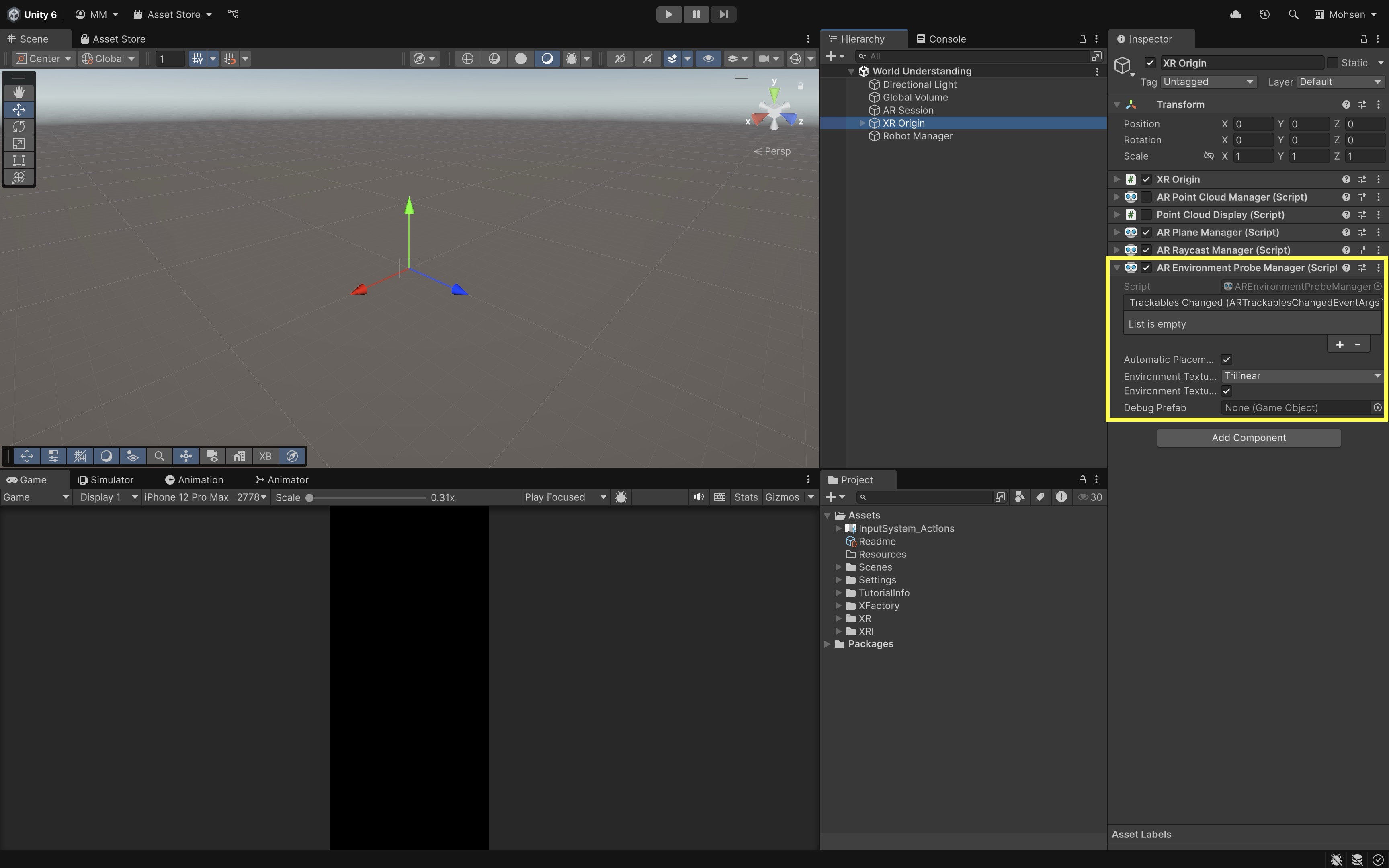
- In the
Hierarchy, select yourXR OriginGameObject. - Click
Add Component > AR Environment Probe Manager. - In the
Inspector, configure the following settings:Automatic Placement: Enable if your provider supports automatic probe placement based on visible surfaces and lighting.Environment Texture Filter Mode: Choose fromPoint(fastest, lowest quality),Bilinear(balanced), orTrilinear(smoothest lighting transitions but higher GPU cost).Environment Texture HDR: Enable for more realistic lighting using high dynamic range cubemaps when supported.Debug Prefab: Optionally, assign a small visual prefab (like a semi-transparent sphere) to see where probes are instantiated during runtime.
Testing and Validation
Validate spatial-awareness features on the hardware and environments your app targets:
| Test target | What to verify |
|---|---|
| XR Simulation | Early scene logic, plane/raycast/occlusion iteration without a physical device |
| Mobile device build | Camera feed, touch input, plane detection, point cloud density, lighting, permissions, thermal behavior |
| Supported depth/mesh device | Meshing, occlusion, environment probes, mesh collider behavior |
| Quest passthrough AR | Provider-supported raycasts, planes, meshes, occlusion, anchors, headset input, passthrough quality |
| Real environment | Lighting, low-texture surfaces, reflective objects, moving people, scale, drift, and safety |
AI-generated AR spatial-awareness scripts often mix legacy touch input, old session-origin wording, unsupported provider features, and expensive per-frame object instantiation. When spatial features fail, verify the provider, physical-device support,
AR Session,XR Origin, managers, permissions, feature availability, and runtime performance before rewriting the scene.
Key Takeaways
- Spatial awareness is only as reliable as the physical environment, sensor hardware, and active provider.
- Point clouds are useful for tracking/debugging, while planes and raycasts are usually better for stable object placement.
- Plane alignment is broadly useful, but semantic classification, meshing, occlusion, and environment probes are provider-dependent.
- Meshes and occlusion improve realism, but they are not validated robot safety or collision systems.
- Engineering AR must be tested on physical devices for scale, drift, lighting, reflective surfaces, performance, and task safety.