D7. Spatial User Interfaces in VR
Learning Outcomes
- Describe the role of spatial UIs in VR environments. Before class, review how immersive UIs support interaction, control, and feedback, drawing on engineering examples like CNC HMIs, teach pendants, and super displays in the XFactory environment.
- Configure world-space UI with current XRI components. For pre-class work, confirm
XR UI Input Module,Tracked Device Graphic Raycaster, and UI-enabled XRI interactors on a world-space Canvas.- Compare VR UI interaction methods. Ahead of the session, review ray/near-far UI pointing, poke/direct UI interaction, and Spatial Keyboard text entry.
- Explain how VR UIs function as input systems. Study how components such as buttons, toggles, and sliders can trigger actions like animations or custom scripts, focusing especially on the CNC HMI example.
- Explain how VR UIs function as output systems. Explore how UIs convey system status, warnings, and environmental data, using the logistics scale example that outputs weight and visual alerts as a reference.
- Evaluate VR UI for engineering use. Assess readability, reachability, safety, error recovery, unit clarity, and task-flow correctness in headset testing.
- Apply best practices for VR UI design. Identify key principles—such as clarity, performance, or ergonomic design—and reflect on how they improve trust, comfort, and usability in VR engineering contexts.
User Interfaces in VR
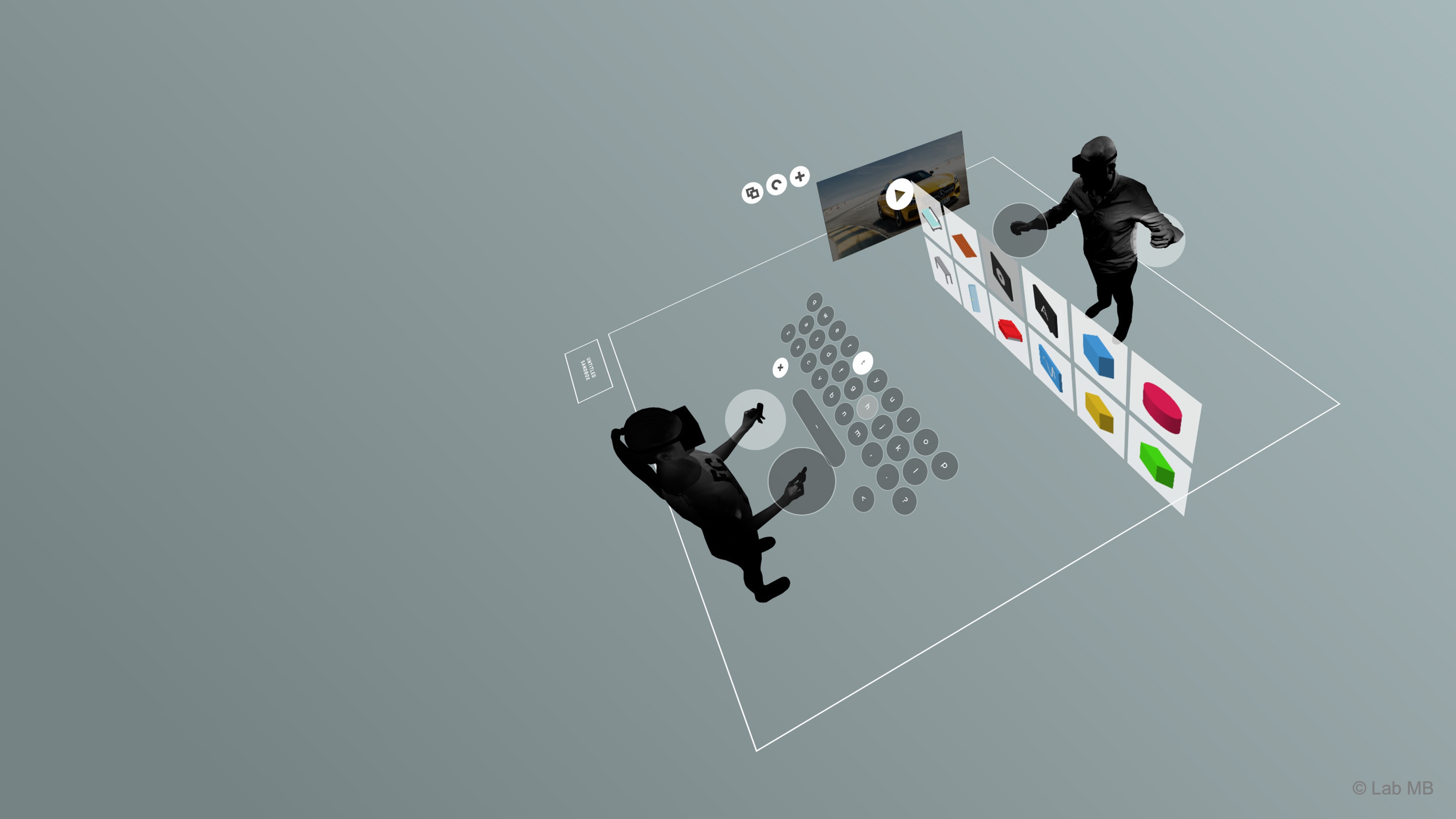
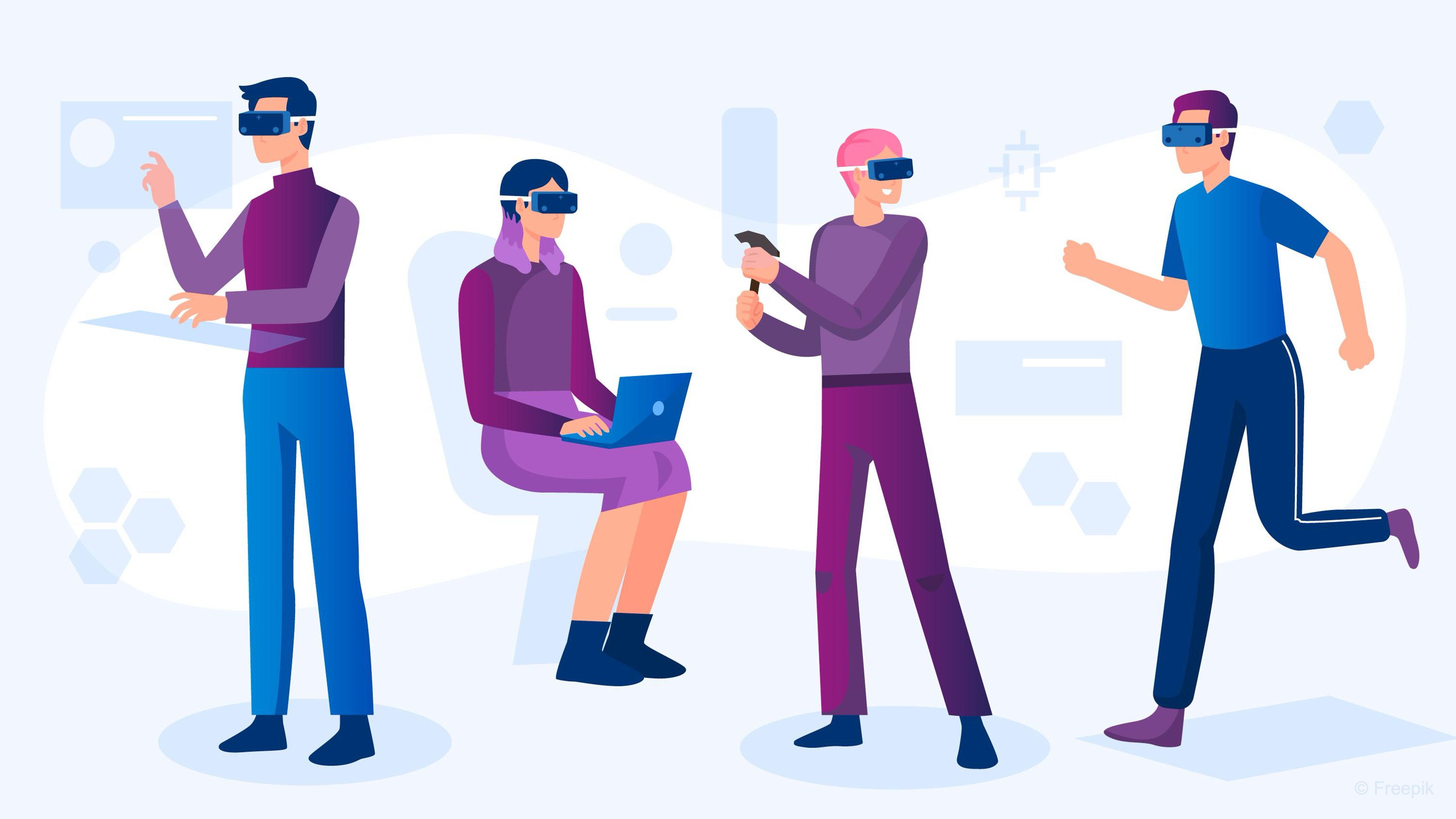
User interfaces (UIs) in VR form the connection between the user and the virtual environment, enabling inputs that influence the system and providing outputs that communicate feedback or change. Examples include virtual control panels for machines, immersive dashboards for real-time monitoring, and collaborative 3D workspaces. Well-designed VR UIs create intuitive, spatial interactions that let users engage with digital representations of real systems naturally and effectively.
Definitions
- User Interface (UI): In VR, a UI is a spatial, interactive element within the 3D world, functioning as both input and output. For example, in XFactory, the robot teach pendant acts as a floating tablet beside the UR10e robot. Users interact to start sequences or jog joints (input), and the interface responds through visual highlights, sound cues, or haptic feedback (output).
- World Space UI: A UI rendered directly in 3D space like any other scene object. This approach supports natural interaction (input) and visible or sensory response (output). In XFactory, the CNC HMI appears as a wall-mounted panel—users touch buttons or sliders to control processes (input), and the panel displays live data such as spindle speed or system status (output). World space canvases typically use the
Tracked Device Graphic Raycastercomponent to receive events from XR interactors such as rays or pokes. - Screen Space UI: A UI attached to the user’s view rather than the world. While less immersive, it is useful for persistent output elements like status overlays, calibration instructions, or safety warnings that must remain visible regardless of orientation.
- Near-Far Interactor: In current Starter Assets workflows, UI is often driven by a
Near-Far Interactorwith UI interaction enabled. It supports combined near/far interaction and can drive UGUI through far-caster UI data. - XR Ray Interactor: A component that projects a laser-style ray from a controller or hand, allowing users to interact with UI elements from a distance. Dedicated
XR Ray Interactorsetups remain useful for specialized far-only panels. In the curved display of the exhibit station, ray interaction allows users to browse data, play tutorials, or filter metrics with minimal movement. - XR Poke Interactor: Poke-style UI interaction can be useful for close physical panel presses where the user should interact as if touching a real HMI button.
- Event System: Unity’s framework that routes user actions to UI elements. In VR, it uses the XR UI Input Module, which integrates with the XR Interaction Toolkit and the Input System. Remove or avoid
Standalone Input Modulefor XR UI. This ensures controller or hand interactions—whether via raycasting or direct touch—trigger familiar UI events likeOnClickorOnValueChanged. In XFactory, when the user presses the “Emergency Stop” button (input), the system displays alert indicators and initiates shutdown sequences (output).
Key Concepts
- UI as Interaction: In VR, UIs act as the primary interface for both command and communication. Users perform deliberate actions—pressing buttons, moving sliders, or pointing with ray interactors—to control machines or change system states (input). In return, the environment responds with visual, auditory, or haptic cues that confirm actions and display current system status (output). For instance, the robot teach pendant lets users jog joints or start routines, while the CNC HMI panel visually updates spindle speed or alerts after each user action.
- Spatial Context: Because UIs exist in 3D space, their placement and scale must support depth perception and movement. Interfaces like the robot teach pendant sit within comfortable reach, while large displays such as the exhibit station’s curved screen are positioned for clear visibility from a distance—encouraging natural head and body motion.
- Feedback and Responsiveness: Every user action should trigger immediate, multimodal feedback. When users press “Start Spindle” on the CNC HMI, a sound plays, the button animates, and the system display updates. This synchronized response reinforces cause and effect, making interactions feel tangible and reliable.
- Visual Integration: UI design should blend with the virtual environment’s logic and aesthetics. Industrial panels use realistic frames, materials, and colors that match the surrounding machinery. Even though interactive, these panels maintain immersion by looking like part of the physical world.
- Ergonomics and Clarity: UI elements must accommodate hand or controller size, movement range, and comfort. Buttons on the teach pendant are large and well spaced to prevent accidental touches, while critical controls like “Emergency Stop” use clear color and position cues. Consistent button styles, icons, and text across all stations reduce confusion and make the system intuitive to navigate.
Design Principles
- Leverage Spatial Interaction: Design interfaces that take advantage of VR’s 3D nature. The curved display in the exhibit station surrounds the user for a panoramic data view, while the teach pendant automatically orients toward the user’s gaze for optimal readability.
- Match Interaction Method to Context: Use direct touch for close, precise tasks and ray-based interaction for distant or large-scale interfaces. The CNC panel supports tactile-style input, while the exhibit display favors ray pointing. The teach pendant flexibly switches between both modes depending on user proximity.
- Maintain Performance Efficiency: VR UI systems can be performance-heavy. Optimize by batching canvases, minimizing overdraw, and using lightweight materials. In XFactory, large displays remain responsive even under load, ensuring smooth interaction across devices.
- Ensure Accessibility and Adaptability: Interfaces should adjust to user needs. The super display includes settings for text scaling and contrast, while the teach pendant dynamically repositions to accommodate different heights or seated users—ensuring comfort and inclusivity for all participants.
UI as Input
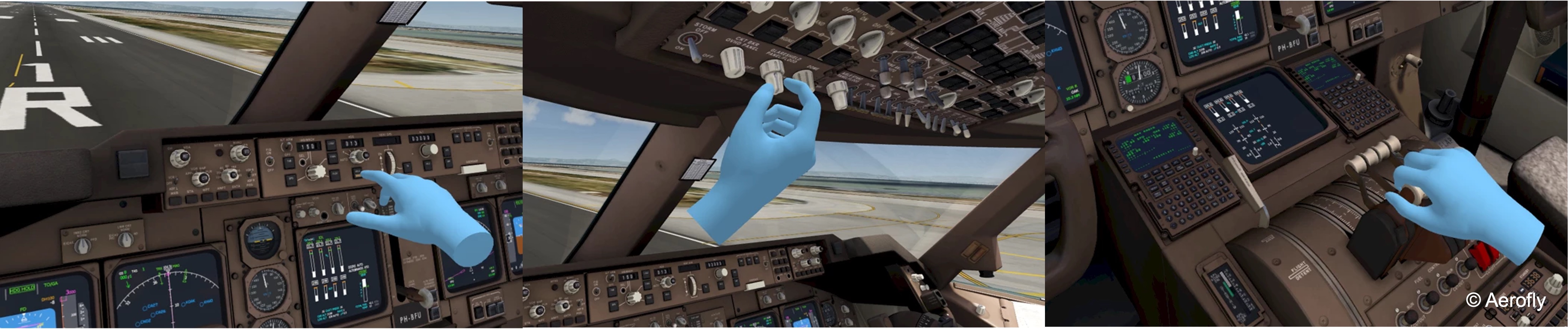
In VR, UI serves as a primary means of user input, allowing users to interact with digital systems as they would with real-world objects. UI as input enables the triggering of actions such as starting a motor, toggling power, or initiating sequences. These inputs often simulate pressing physical buttons, adjusting sliders, or flipping switches in a spatial, embodied context. In engineering scenarios, UI as input can replicate real industrial control logic, where a physical interface sends signals to a machine. In VR, we map this interaction into 3D space using Unity’s XR Interaction Toolkit.
UI Input Elements
UI input elements are the core components that let users control and interact with systems in VR. They translate physical-like gestures—pressing, sliding, pointing, or typing—into digital signals that drive behavior in the virtual environment. For engineering HMIs, label units and states clearly, use consistent colors, and make critical controls such as Power, Stop, and E-Stop visually distinct. A VR UI should not make a machine state look safe unless the underlying simulation state confirms it. Test the HMI in headset: buttons should be reachable, readable, and large enough for controller ray/poke accuracy without causing accidental presses.
- Virtual Buttons and Switches: Trigger discrete or toggle-based actions. Buttons typically perform immediate commands (e.g., “Start,” “Stop”), while switches maintain ongoing states like power, mode, or safety status.
- Toggles and Sliders: Toggles emulate on/off switches, and sliders control continuous variables such as speed, pressure, or feed rate. Their design should allow fine adjustment and clear visual indication of current value.
- Touch and Ray Interaction: UIs can be operated through direct touch (hand or controller contact) or remotely via ray interaction. The method depends on distance and task context—close-range panels favor touch, while large or distant displays work best with rays.
- Dropdowns and Scrollbars: Enable selection from multiple options or navigation through extended content. In VR, these should be simplified, large, and responsive to avoid precision issues caused by controller movement or hand tracking.
- Input Fields and Virtual Keyboards: Allow users to enter text or numeric data. When selected, an on-screen virtual keyboard appears—either attached to the panel or floating near the user’s view. Keys are pressed via ray or direct touch, with visual and audio feedback confirming each input. This is useful for entering machine parameters, naming saved configurations, or typing short commands without leaving the VR context.
- Gestural Zones and Proximity Triggers: Regions or sensors that detect user presence or motion, triggering actions without explicit button presses. For instance, stepping into an interaction zone may wake a UI, or a hand gesture may confirm an operation—reducing interface clutter and maintaining immersion.
The scene EventSystem must use
XR UI Input Module. Remove or avoidStandalone Input Modulefor XR UI. The world-space Canvas must haveTracked Device Graphic Raycaster. The interactor (typicallyNear-Far Interactor) must have UI interaction enabled. UIGraphiccomponents needRaycast Targetenabled to receive hits. Canvas scale and position matter because world-space UI uses real scene units. Standard Unity UI ray interaction does not require a physics collider, but physical/poke-style interaction may require additional setup depending on the interactor workflow.
Interactive UI Elements
Let’s implement a fully interactive VR UI panel on the CNC lathe machine (CNC_Lathe) in the manufacturing station. Users will be able to POWER the machine on/off (i.e., turn machine ON/OFF, play/stop machine sound, and activates/deactivates machine lights), START it (close doors and rotate chuck), and STOP it (open doors and stop chuck). Here is how to set up the UI input and implement this behavior.
- Configure the Machine HMI’s Canvas:
- In the
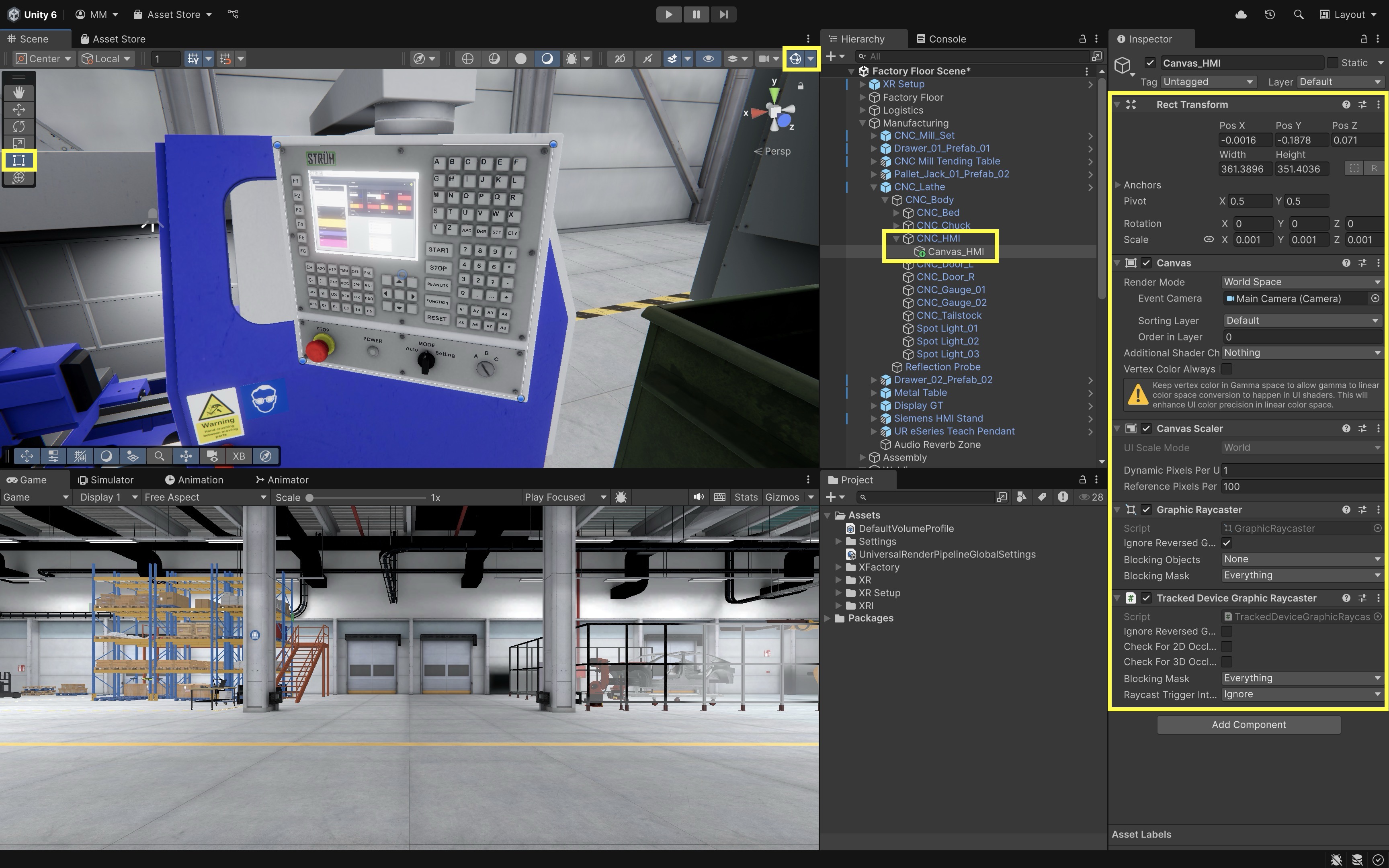
Hierarchy, navigate toManufacturing > CNC_Lathe > CNC_HMI. This is a 3D model representing the machine’s control interface. It does not yet include aCanvasfor UI elements. - Create a world-space Canvas using the
XR > UI Canvasmenu or a standard Unity Canvas configured for world space, then add/verifyTracked Device Graphic Raycaster. - Rename the new object to
Canvas_HMIfor clarity. - Use the gizmos and
Rect Toolto rescale and reposition the Canvas so it fits cleanly on the front face of theCNC_HMImodel. Make sure it is not embedded inside or blocked by the mesh. - Confirm
Render Modeis set toWorld Space. - Ensure the EventSystem uses
XR UI Input Module(removeStandalone Input Module). - Confirm the Canvas includes
Tracked Device Graphic Raycaster.
- In the
- Create Overlay Buttons on the Canvas:
- Under
Canvas_HMI, add three UI controls:PowerButtonas aToggle, plusStartButtonandStopButtonas Unity UI Buttons. To do so, right-click onCanvas_HMIand chooseUI > ToggleorUI > Button - TextMeshPro. - Position each UI button directly over the corresponding 3D button model in the scene.
- Use the
RectTransformto size each button so it matches the shape and boundary of the physical button model. - Select each button’s child
Text (TMP)object and disable or delete it.
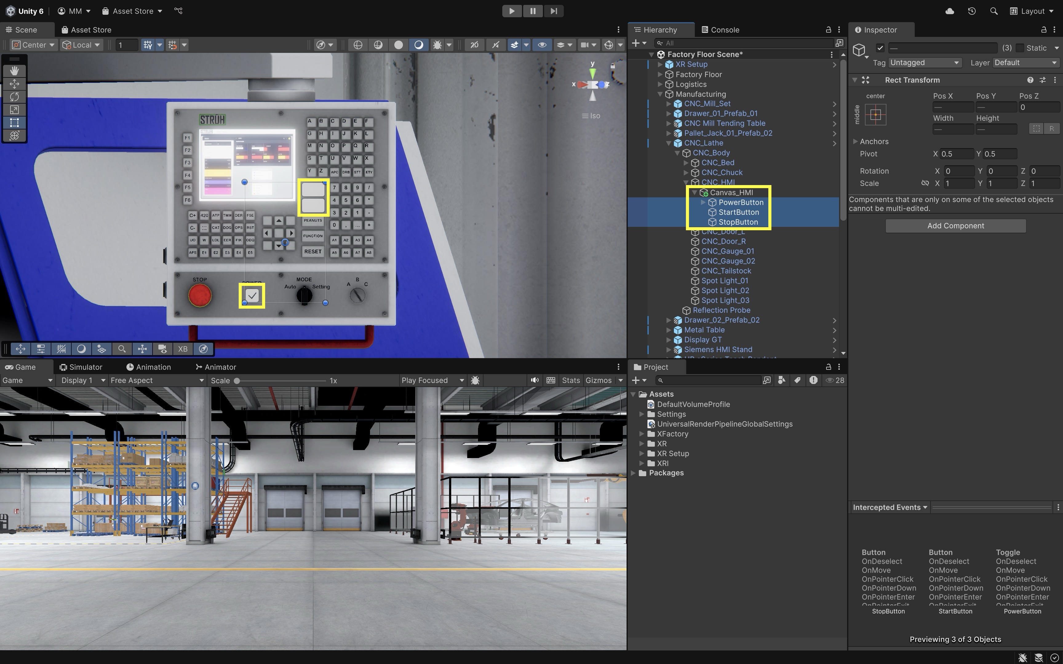
The CNC_HMI model already includes 3D models of the POWER, START, and STOP buttons. Rather than replacing these with visible Unity UI elements, we’ll overlay invisible, functional UI buttons on top of the models to make them interactive.
- Under
- Make Buttons and Toggle Transparent:
- During setup, use a semi-transparent debug color so students can verify alignment. After testing, reduce alpha to 0.
- Select the button objects (
StartButtonandStopButton). - Go to the
Imagecomponent in theInspector. - Set the
A(color alpha) to0(fully transparent). Alternatively, assign a transparent UI sprite as the source image. - Keep the
Imagecomponent’sRaycast Targetenabled even when alpha is 0; otherwise the invisible button will not receive UI interaction. - Disable or delete the child
Text (TMP)element if you haven’t done so already. - Select the toggle object (
PowerButton). - Expand its child hierarchy.
- Select the
Backgroundimage. SetAto0. - Select the
Checkmarkimage. SetAto0. - Disable or delete the
Label(TMP) object if you haven’t done so already. - Invisible UI can be difficult to debug. If interactions fail, temporarily make the overlay visible.
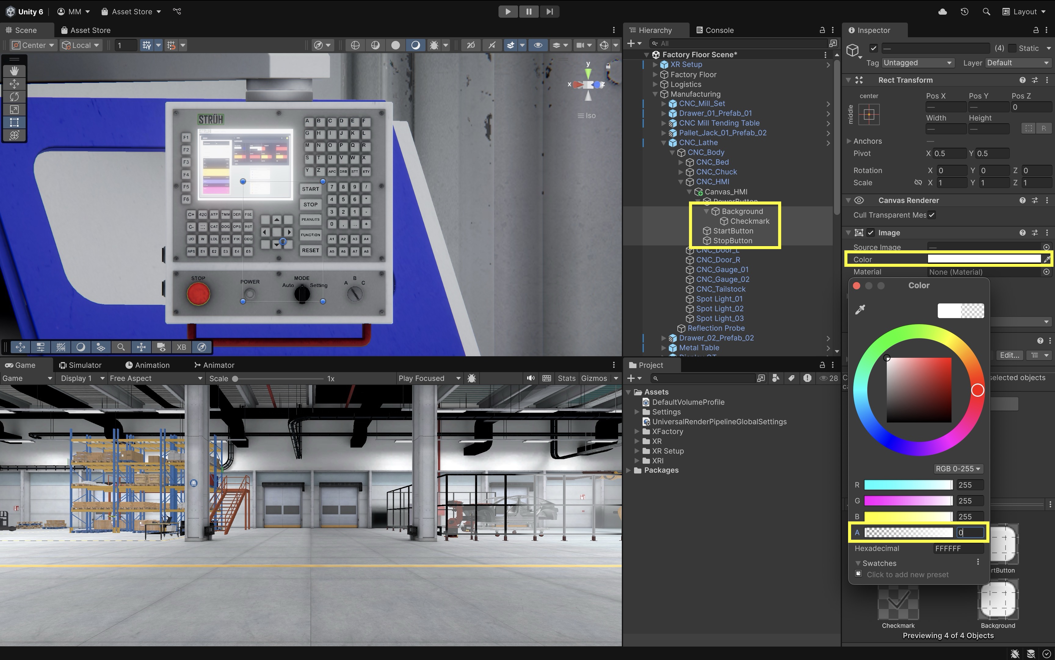
These steps ensure the UI components remain invisible but fully functional, enabling interaction through ray or touch without obscuring the 3D button models.
- Confirm Interaction Readiness:
- Ensure the Canvas includes a
Tracked Device Graphic Raycaster. - Ensure buttons have
Interactableenabled (Toggle > InteractableandButton > Interactable). - Leave space between buttons to prevent accidental interaction.
At runtime, the user will see only the original button models, but interaction will be handled via the overlaid invisible Unity UI buttons. This preserves the realism of the HMI panel while enabling XR input support.
- Ensure the Canvas includes a
- Prepare Scene Elements for Interaction:
- Attach an
AudioSourceto the CNC machine for machine sound. If the sound represents machine noise in the scene, setSpatial Blend = 1with reasonableMin Distance/Max Distance, and route it through an Audio Mixer if available. For short UI confirmation clicks, use a non-looping beep instead of a machine-loop clip. - Locate the three machine light GameObjects (
Spot Light_01,Spot Light_02,Spot Light_03). - Locate the chuck (the rotating part of the machine) GameObject (
CNC_Chuck). - Locate the left and right door GameObjects (
CNC_Door_L,CNC_Door_R).
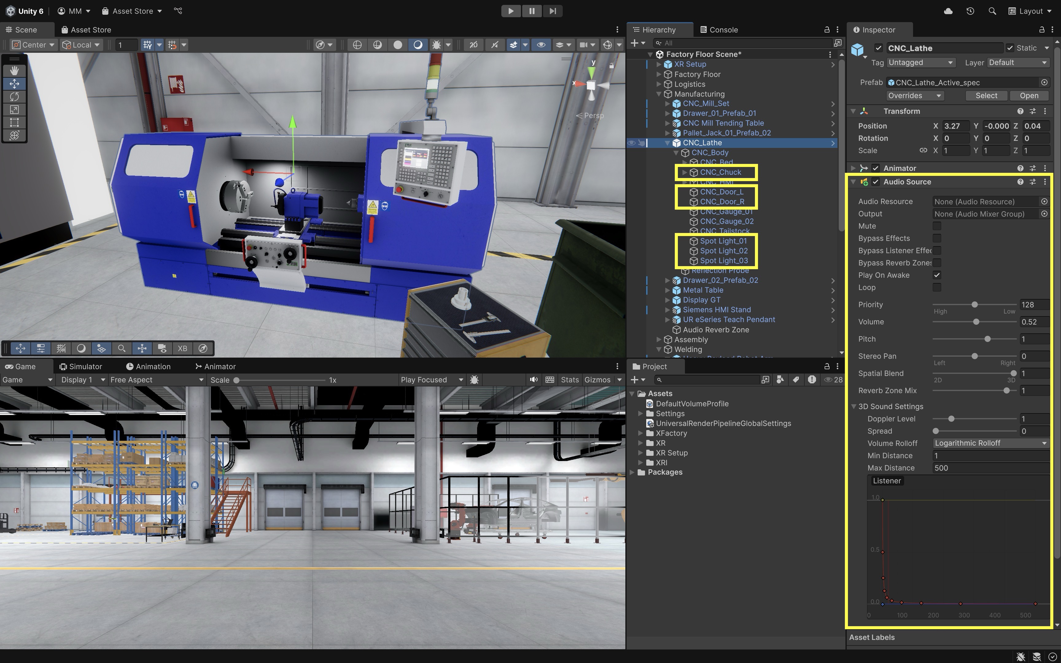
- Attach an
- Script the Chuck Rotation Behavior:
- Create the following script and attach it to the
CNC_ChuckGameObject to enable/disable rotation. This a prerequisite for scripting the HMI behavior as discussed next.
using UnityEngine; public class ChuckRotator : MonoBehaviour { [SerializeField] private float rotationSpeed = 180f; [SerializeField] private bool isRotating; private void Update() { if (isRotating) transform.Rotate(Vector3.right, rotationSpeed * Time.deltaTime, Space.Self); } public void SetRotating(bool value) { isRotating = value; } } - Create the following script and attach it to the
- Configure the Script:
Rotation Speed: Set to180(or adjust for desired RPM effect).Is Rotating: Leave unchecked by default. This will be controlled by the HMI script at runtime.
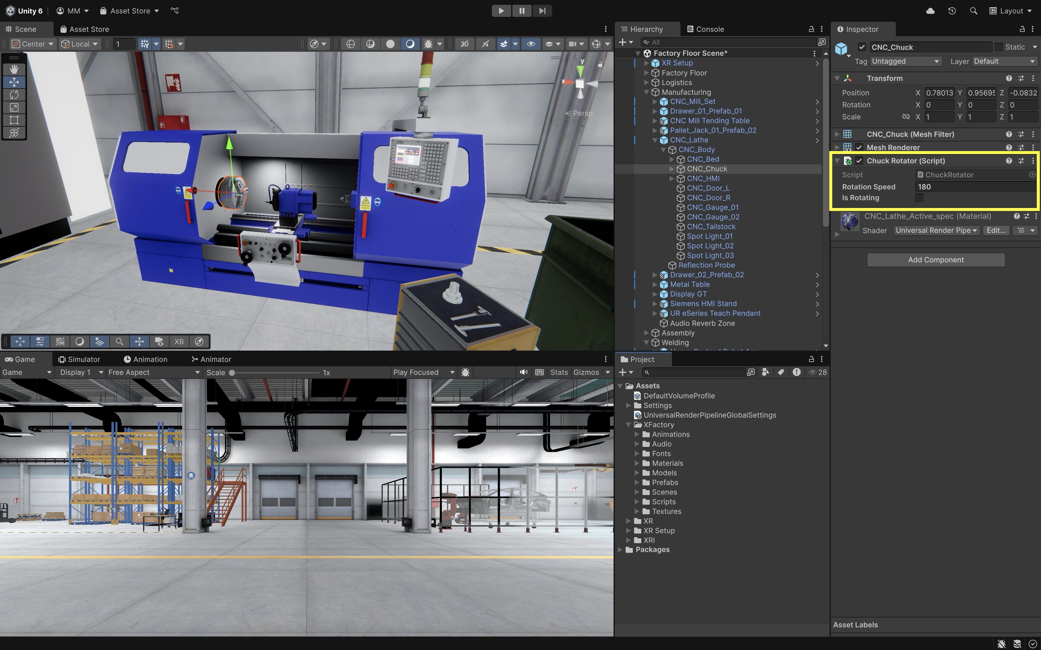
- Script the HMI Behavior:
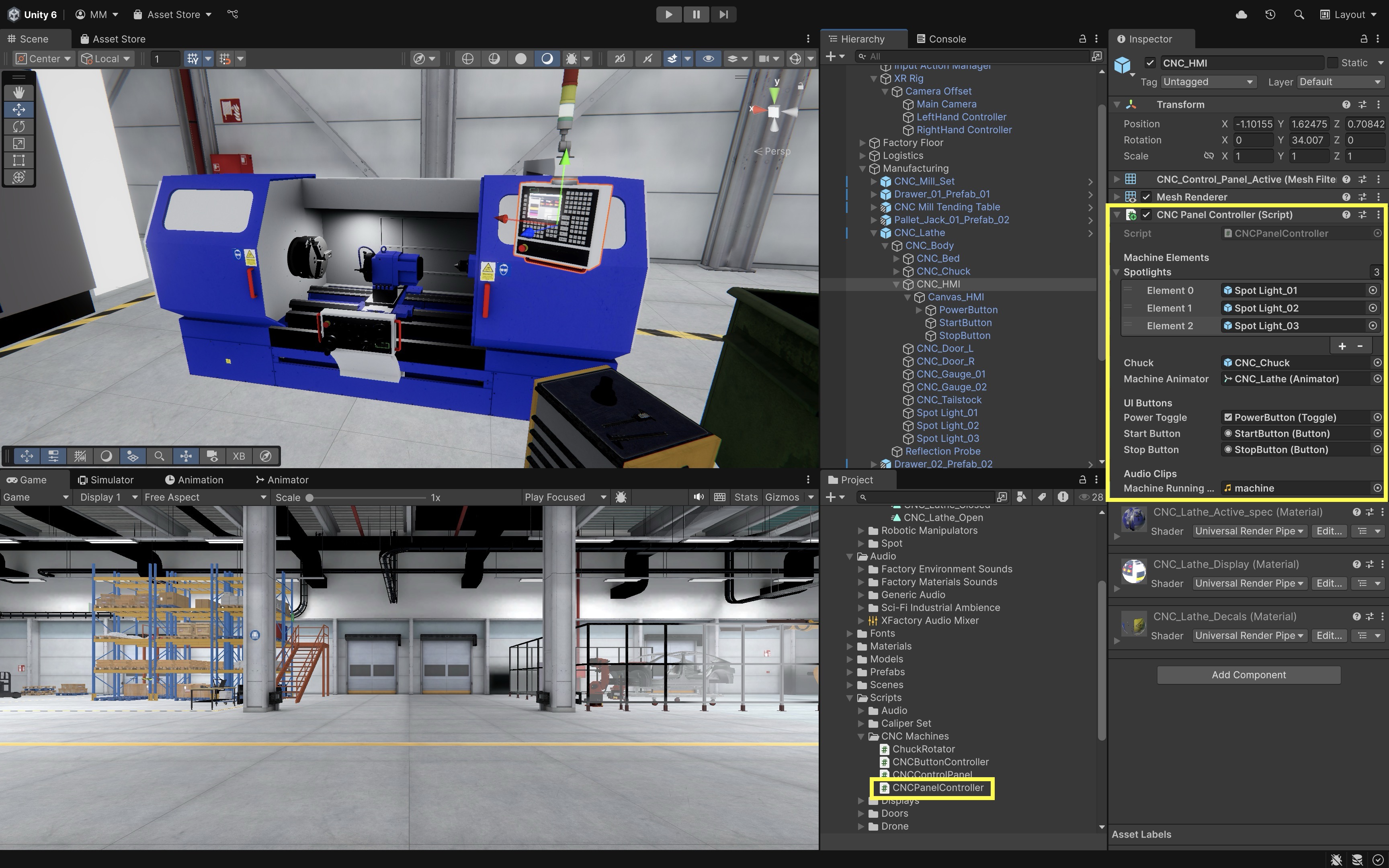
- Attach the following script to
Canvas_HMI. - This script handles input events from buttons and triggers machine animation and chuck control based on user interaction.
- A VR HMI should model safe command states. Disable or ignore commands that do not make sense, such as Start while already running or Stop while idle.
using UnityEngine; using UnityEngine.UI; using TMPro; [RequireComponent(typeof(AudioSource))] public class CNCPanelController : MonoBehaviour { [Header("Machine Elements")] [SerializeField] private GameObject[] spotlights; [SerializeField] private ChuckRotator chuckRotator; [SerializeField] private Animator machineAnimator; [Header("UI Controls")] [SerializeField] private Toggle powerToggle; [SerializeField] private Button startButton; [SerializeField] private Button stopButton; [SerializeField] private TextMeshProUGUI statusText; [Header("Audio")] [SerializeField] private AudioClip machineRunningClip; private AudioSource audioSource; private bool isMachineOn; private bool isRunning; private void Awake() { audioSource = GetComponent<AudioSource>(); if (audioSource == null) { Debug.LogWarning("CNCPanelController: AudioSource is missing."); return; } audioSource.playOnAwake = false; audioSource.loop = true; audioSource.spatialBlend = 1f; } private void OnEnable() { if (powerToggle != null) powerToggle.onValueChanged.AddListener(OnPowerToggle); if (startButton != null) startButton.onClick.AddListener(OnStartPressed); if (stopButton != null) stopButton.onClick.AddListener(OnStopPressed); UpdateStatusDisplay(); } private void OnDisable() { if (powerToggle != null) powerToggle.onValueChanged.RemoveListener(OnPowerToggle); if (startButton != null) startButton.onClick.RemoveListener(OnStartPressed); if (stopButton != null) stopButton.onClick.RemoveListener(OnStopPressed); } private void OnPowerToggle(bool isOn) { isMachineOn = isOn; if (isOn && machineRunningClip != null && audioSource != null) { audioSource.clip = machineRunningClip; audioSource.Play(); } else if (audioSource != null) { audioSource.Stop(); } SetMachineLights(isOn); if (!isOn) { isRunning = false; SetChuckRotation(false); TriggerDoorAnimation("Open_Doors"); } UpdateStatusDisplay(); } private void OnStartPressed() { if (!isMachineOn || isRunning) return; TriggerDoorAnimation("Close_Doors"); SetChuckRotation(true); isRunning = true; UpdateStatusDisplay(); } private void OnStopPressed() { if (!isMachineOn || !isRunning) return; SetChuckRotation(false); TriggerDoorAnimation("Open_Doors"); isRunning = false; UpdateStatusDisplay(); } private void SetChuckRotation(bool rotate) { if (chuckRotator == null) { Debug.LogWarning("CNCPanelController: ChuckRotator is not assigned."); return; } chuckRotator.SetRotating(rotate); } private void SetMachineLights(bool enabled) { if (spotlights == null) return; foreach (var light in spotlights) { if (light != null) light.SetActive(enabled); } } private void TriggerDoorAnimation(string triggerName) { if (machineAnimator == null) { Debug.LogWarning("CNCPanelController: Machine Animator is not assigned."); return; } machineAnimator.SetTrigger(triggerName); } private void UpdateStatusDisplay() { if (statusText != null) { if (!isMachineOn) statusText.text = "OFF"; else if (isRunning) statusText.text = "RUNNING"; else statusText.text = "READY"; } if (startButton != null) startButton.interactable = isMachineOn && !isRunning; if (stopButton != null) stopButton.interactable = isMachineOn && isRunning; } } - Attach the following script to
- Configure the Script:
- Machine Elements:
Spotlights: Add all 3 spotlight GameObjects to the array.Chuck Rotator: Drag theCNC_ChuckGameObject (must haveChuckRotator.csscript).Machine Animator: Drag theCNC_LatheGameObject that has the Animator with theOpen_DoorsandClose_Doorstriggers. - UI Controls:Power Toggle: Drag theToggleUI element for the Power button.Start Button: Drag theButtonUI element for Start.Stop Button: Drag theButtonUI element for Stop.Status Text: Drag aTextMeshProUGUIfield on the HMI canvas forOFF,READY, orRUNNING. - Audio Clips:Machine Running Clip: Drag the looping audio file to play while the machine is powered on.
- Play and Test in VR:
- Enter Play Mode with Quest Link / Meta Horizon Link for rapid preview, then test with Android Build and Run on Quest.
- Point at the invisible UI areas over the HMI buttons and use your VR controller or hand tracking to interact.
- Toggle Power and watch the spotlights turn on/off, machine sound start/stop, and status text update.
- Press Start to see the chuck begin rotating and doors close automatically.
- Press Stop to halt rotation and open the doors.
- Verify Start is ignored while already running and Stop is ignored while idle.
- Check that all actions feel natural in VR, with no accidental button presses or alignment issues.
- XRI UI Troubleshooting Checklist:
- EventSystem has
XR UI Input Module. - Canvas is
World Space. - Canvas has
Tracked Device Graphic Raycaster. - UI interactor has UI interaction enabled.
- UI overlay Images have
Raycast Targetenabled. - Buttons are not blocked by another Canvas/Graphic.
- Button
OnClickfires once. - Button hit areas align with the visible 3D HMI model.
- UI is readable and reachable in headset.
- Quest Link / Meta Horizon Link preview works.
- Android build-to-device test works on Quest.
- EventSystem has
- Optional Extensions:
- Add button glow/color feedback on press, haptic confirmation through
Simple Haptic Feedback, or smoother door/light transitions. - To further improve realism, consider animating door movement instead of snapping their positions or fading spotlights in and out smoothly rather than toggling instantly.
This entire system demonstrates UI as input—the user presses buttons that cause state changes in the virtual environment, such as turning the machine on/off, starting/stopping the chuck, or opening/closing doors—and UI as output through the status text and button interactability.
- Add button glow/color feedback on press, haptic confirmation through
Spatial Keyboard
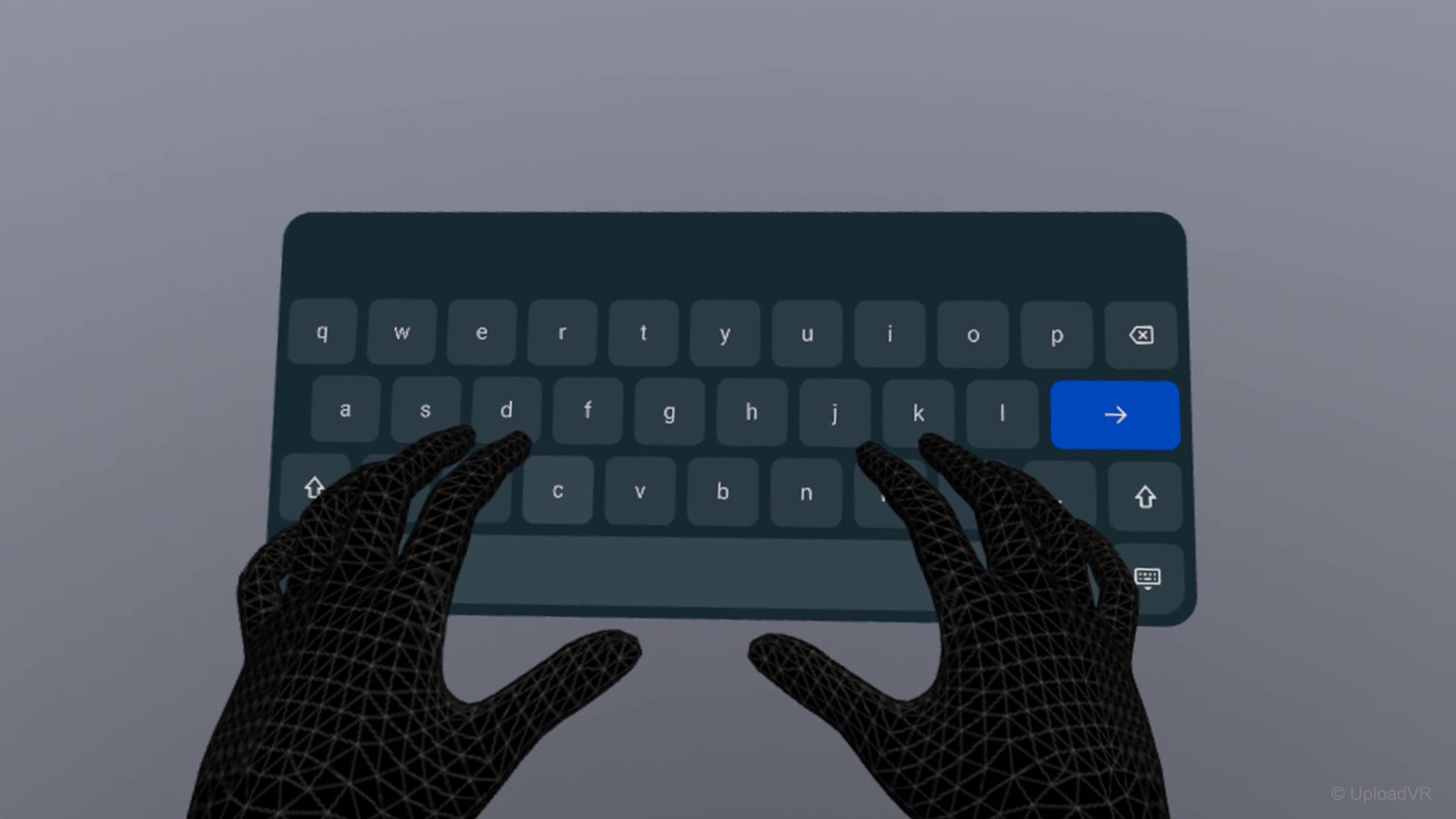
In VR, typing can be tricky since users don’t have access to a physical keyboard. A spatial keyboard solves this by letting users enter text directly inside the virtual world—for example, to name files, send chat messages, or fill in login fields. The XR Interaction Toolkit’s Spatial Keyboard sample provides a built-in solution that works with TextMesh Pro (TMP) input fields and responds naturally to XR ray or direct interactors. Prefab names and fields can vary by XRI version, so verify the imported sample in the Inspector.
- Import the Sample:
- Go to
Window > Package Management > Package Manager > XR Interaction Toolkit > Samples. - Import
Spatial Keyboard.
- Go to
- Make Prefabs:
- Import the Spatial Keyboard sample from the XR Interaction Toolkit package. Use the sample prefabs/scripts provided by the installed version, and verify names/fields in the Inspector.
- If your imported sample uses prefabs such as
XRI World KeyboardandGlobal Keyboard Manager, drag them into yourProjectwindow and save prefab variants as needed.
- Add to Your Scene:
- Open your
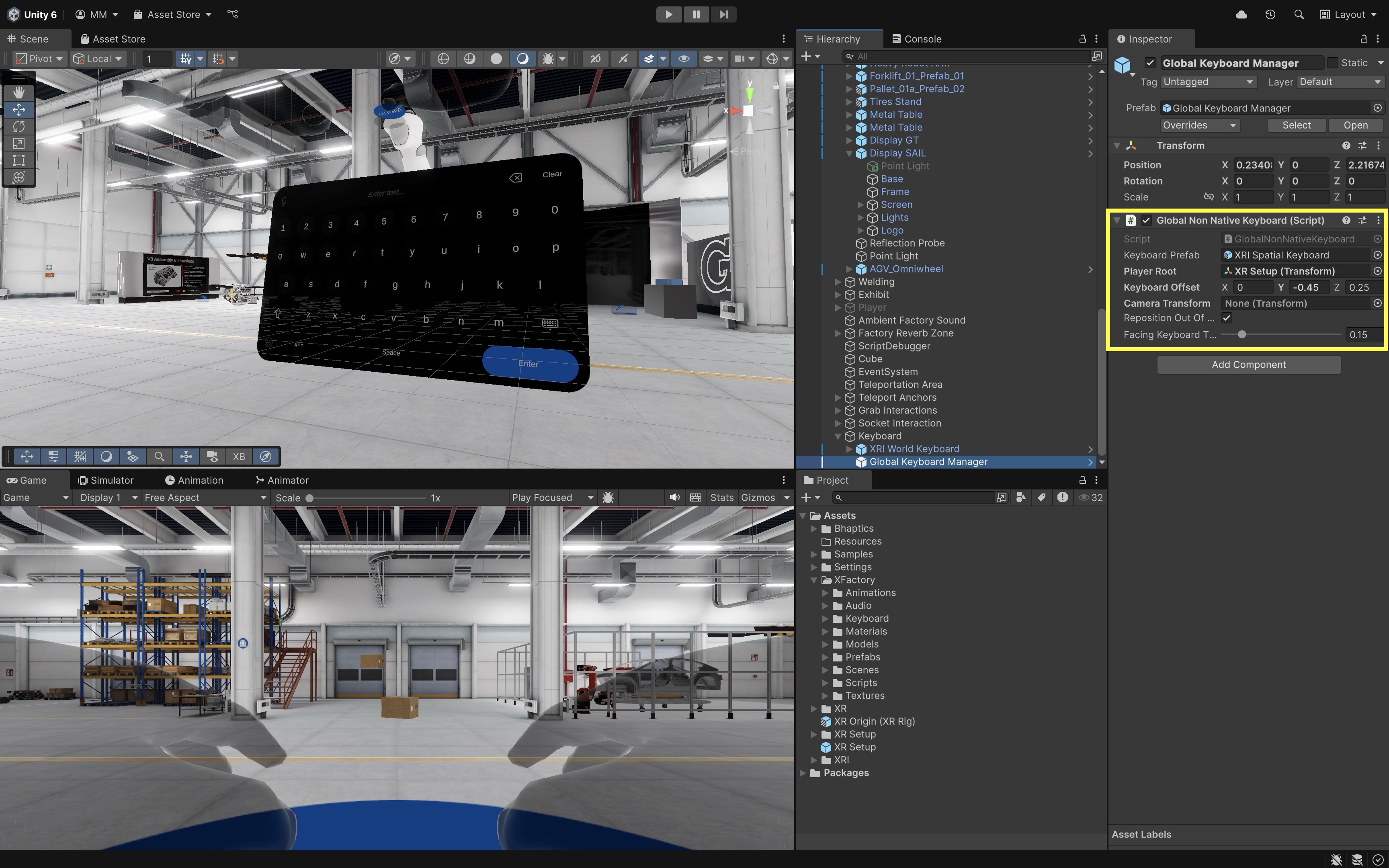
XFactoryVRscene and drag the sample prefabs in. - If your imported sample uses prefabs such as
XRI World KeyboardandGlobal Keyboard Manager, place them in the scene and assign the copiedXR Origin (XR Rig)(or the player/root reference shown by the sample) and TMP input field references shown by the Inspector. - Position the keyboard and manager at the scene root or as recommended by the sample.
- Position the
TMP Input Fieldinside a world-space Canvas that can receive XR UI interaction (for example, the large display in the assembly station).
- Open your
- Link Keyboard to Input Field:
- In the world keyboard inspector, assign your TMP_InputField as the target/linked input field shown by the sample.
- Spatial Keyboard works with TMP input fields. Ensure the input field is on a world-space Canvas that can receive XR UI interaction.
- Text entry in VR is slower and more error-prone than desktop typing. Use it for short labels, numeric values, and search/filter fields, not long-form text entry.
- Deploy and Test:
- Enter Play Mode with Quest Link / Meta Horizon Link for rapid preview, then test with Android Build and Run on Quest.
- Click or select the text field in VR, and the keyboard should appear automatically.
- Verify keyboard placement does not block the task panel, hide critical safety information, or require awkward neck/arm posture.
- Use the keyboard icon button on the keyboard to close it when finished typing.
UI as Output
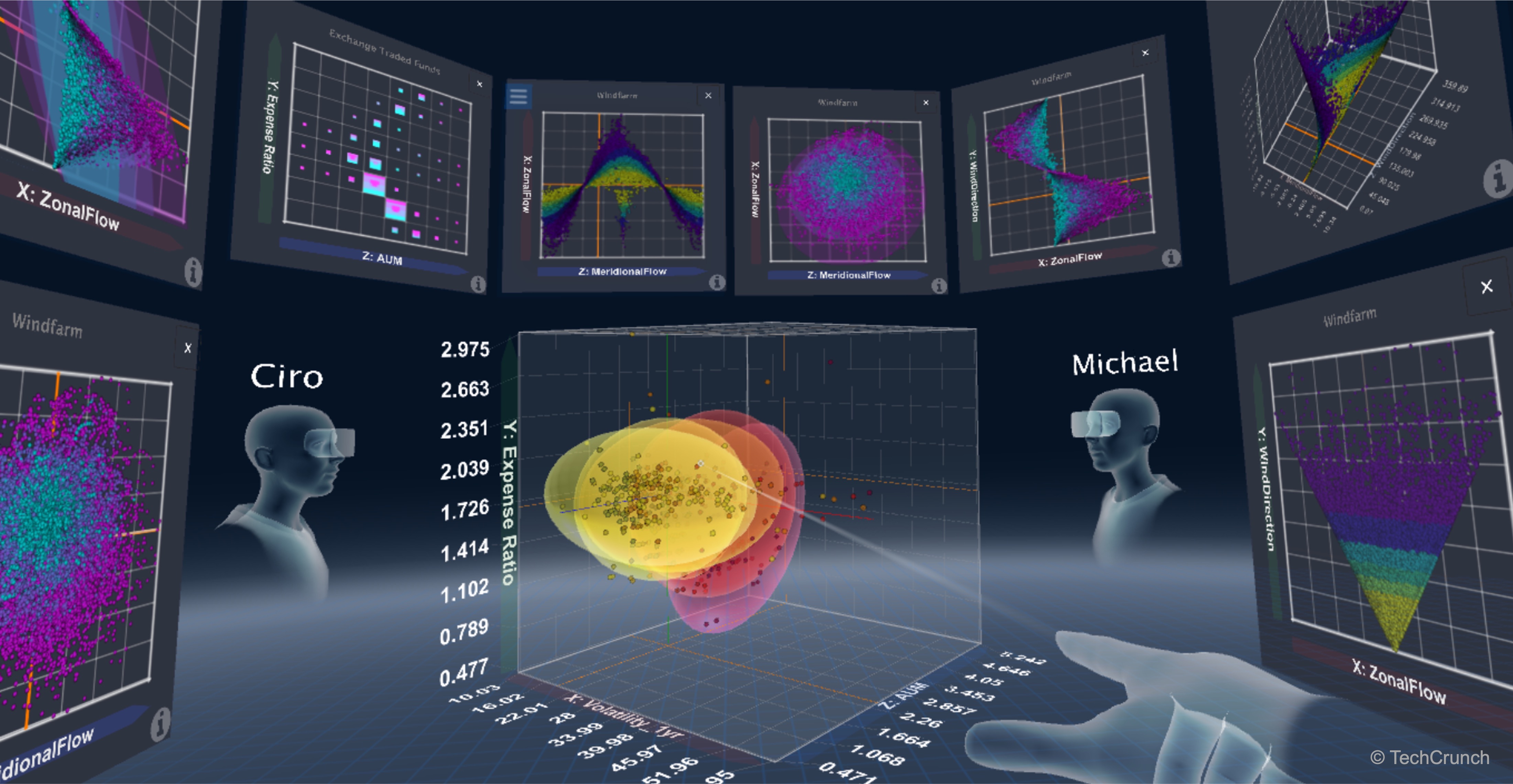
In VR, UI elements serve as critical output channels, displaying information from the environment back to the user. These outputs help users understand system status, receive confirmation of actions, monitor sensor readings, or respond to changing conditions. UI as output mimics real-world feedback systems, like indicator lights, gauges, or control displays, that reflect the internal state of a machine or process. In VR, this concept is extended through dynamic text updates, color changes, flashing indicators, and sound or haptic responses that mirror real-world cues. In Unity, these outputs are typically driven through scripts that update UI elements based on runtime events or data.
UI Output Elements
UI output components visually communicate real-time or event-based data from the virtual environment. These elements often work in tandem with system states or user input to present contextual feedback.
- Dynamic Text Fields: Display numerical or string values (e.g., machine status, object weight, task completion messages) updated via scripts. These fields can reflect constantly changing variables like temperature, load, or runtime conditions in real-world equipment simulations.
- Image Components and Icons: Change sprite, color, or visibility based on system state (e.g., warnings, indicators, error lights). They serve as intuitive visual cues, replacing or enhancing physical LEDs or indicator panels in industrial contexts.
- Animations or Flashing Effects: Draw user attention to critical changes, such as alerts or unsafe conditions. Flashing, pulsing, or movement effects increase visibility and urgency, especially in safety-critical applications.
- Audio or Haptic Feedback: While technically sensory, these often accompany UI output to reinforce state transitions or warnings. Sounds like beeps or buzzers and controller vibrations strengthen immersion and ensure important events are noticed even if not directly seen.
- UI Color States: Color changes (e.g., green = safe, red = warning) are widely used in engineering contexts to indicate output status. These visual conventions provide instant recognition and align with industry-standard signage for hazards and system conditions.
- Graphs, Gauges, and Meters: More complex UIs may visualize data trends or magnitudes, though simplified for VR usability. These elements help users monitor performance or diagnostics over time, useful in training dashboards or factory analytics displays.
UI Display Elements
Let’s create a fully functional HMI display for the Industrial_Scale_01a located in the logistics station. We will simulate a real industrial weighing scale that reads the combined Rigidbody.mass of objects placed on it and outputs that weight to a display. If the total exceeds a configurable maximum weight threshold, the display shows OVERLOAD, the background flashes, and the text remains readable. This example reads Rigidbody.mass; it is not a real sensor. For engineering training, verify that imported objects use realistic mass values and that displayed units, thresholds, and warning states match the intended scenario. Always label units clearly, such as kg or lb, and avoid mixing unit systems.
- Identify and Prepare UI Elements:
- In the
Hierarchy, locateIndustrial_Scale_01a > HMI. - Confirm the HMI contains a
Display Background(anImagecomponent for visual styling) and aDisplay Text: ATextMeshProUGUIcomponent used to show the numeric weight.
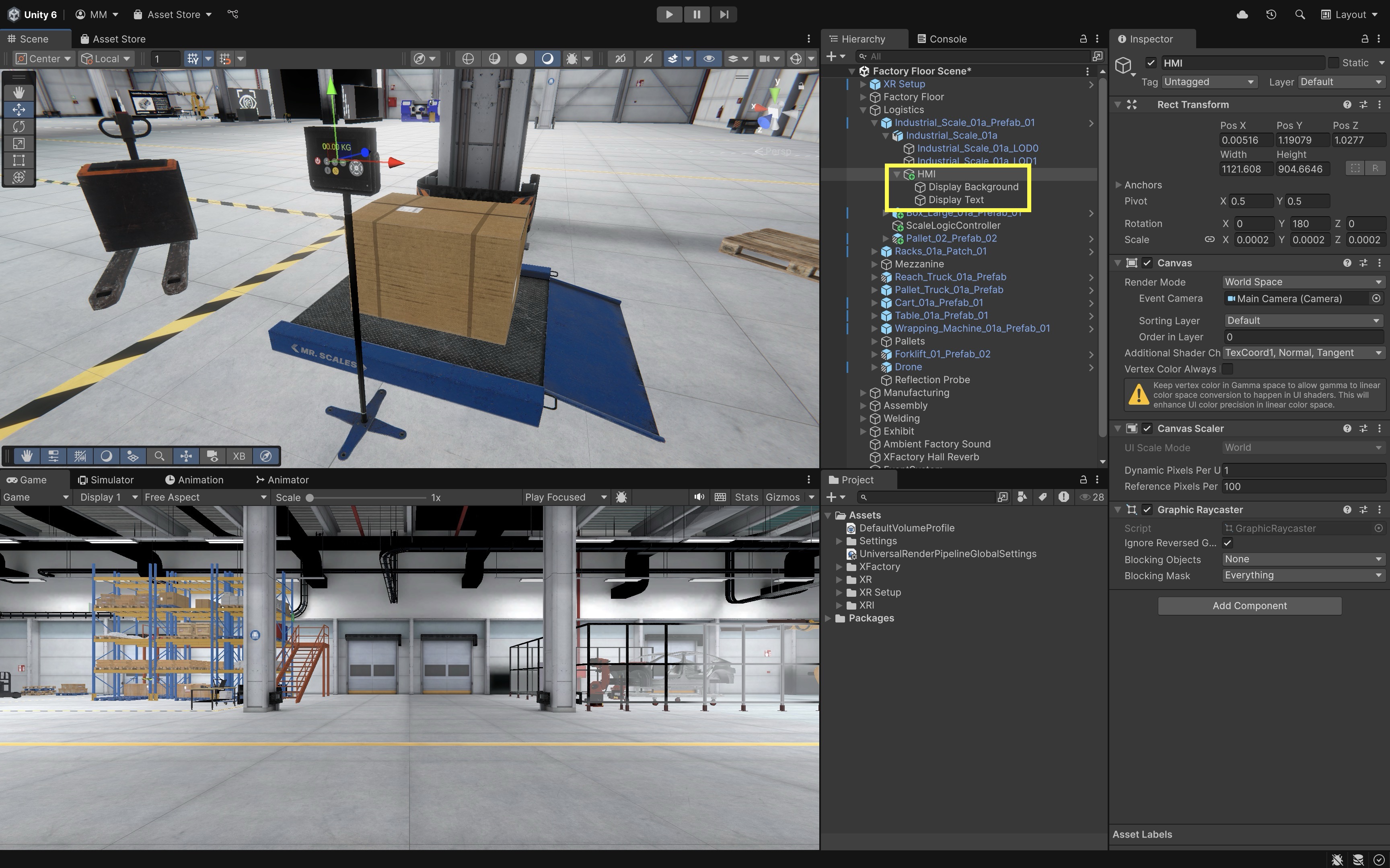
These elements are pre-designed but currently static. We will drive them through a new script that monitors object placement and updates the text dynamically.
- In the
- Add a Trigger Zone for Weighing:
- In the
Hierarchy, right-click onIndustrial_Scale_01aand selectCreate Empty. Rename the new GameObject toWeighing Platform. - Set its
Positionto0, 0, 0, then adjust its local position (via theTransform) so it sits slightly above the actual platform surface, right where the user would place a box or object for weighing. - With
WeighingPlatformselected, go toAdd Componentand add aBox Collider. - In the
Box Collidercomponent, check theIs Triggerbox. - Use the
Box Collider’sCenterandSizevalues to define a tight bounding box that covers only the weighable surface area of the scale.
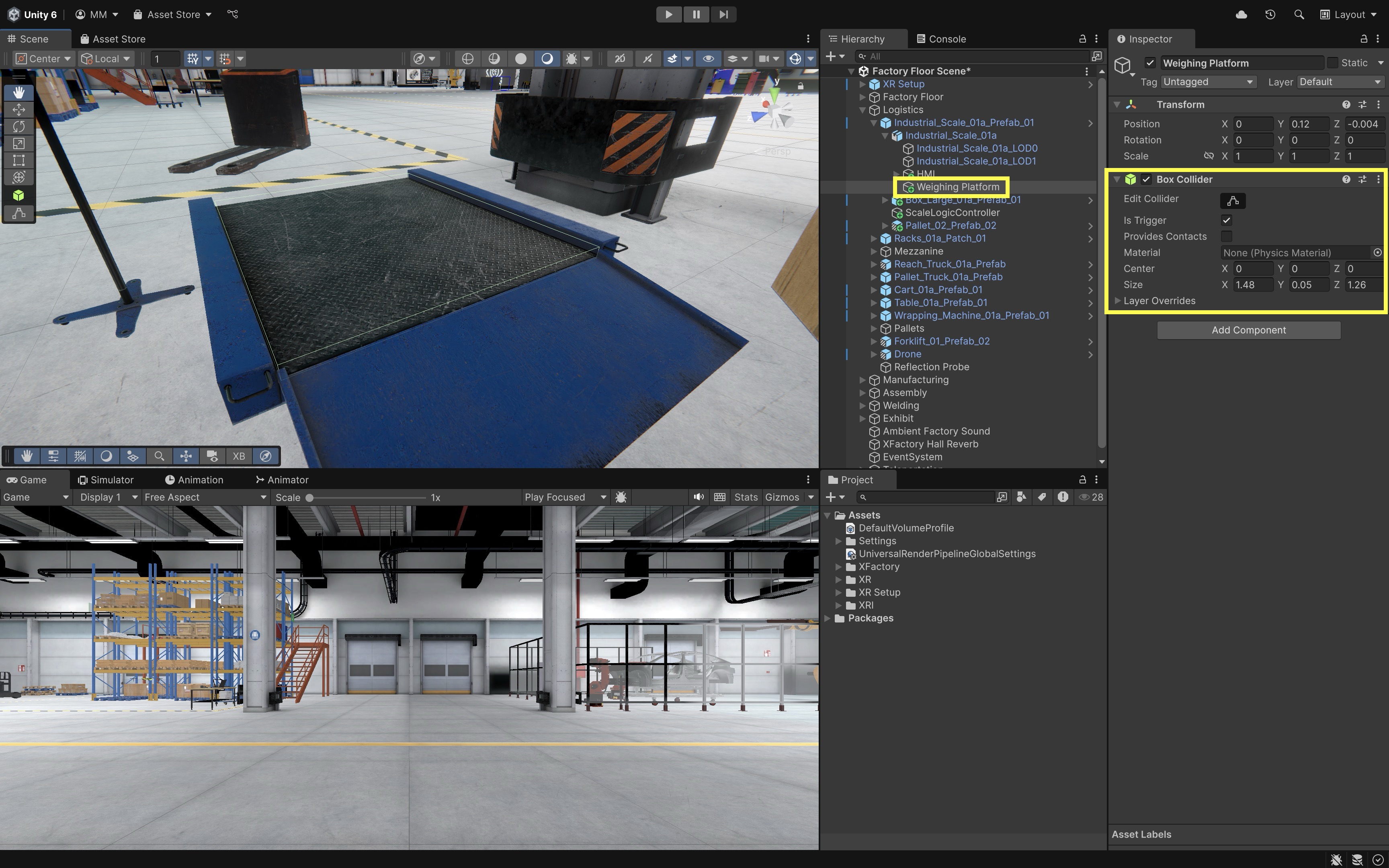
This method avoids modifying the original
Mesh Colliderused for physical collisions, while still enabling trigger-based logic for detecting when objects are placed on the scale. - In the
- Create and Configure the Scale Display Script:
- Create a script called
ScaleDisplay.cs. - Attach it to the
Weighing PlatformGameObject. - For many UI displays, throttle updates rather than changing text every frame. This scale script updates every 0.1 seconds, which is enough for a single platform display.
 using UnityEngine;
 using TMPro;
 using UnityEngine.UI;
 using System.Collections.Generic;

 public class ScaleDisplay : MonoBehaviour
 {
     [Header("Display Components")]
     [SerializeField] private TextMeshProUGUI displayText;
     [SerializeField] private Image displayBackground;

     [Header("Weight Settings")]
     [SerializeField] private float weightThreshold = 50f;
     [SerializeField] private float updateInterval = 0.1f;

     [Header("Flash Settings")]
     [SerializeField] private Color normalColor = Color.green;
     [SerializeField] private Color warningColor = Color.red;
     [SerializeField] private Color normalBackgroundColor = Color.black;
     [SerializeField] private Color warningBackgroundColor = new Color(0.5f, 0f, 0f, 1f);
     [SerializeField] private float flashInterval = 0.5f;

     private readonly HashSet<Rigidbody> objectsOnScale = new HashSet<Rigidbody>();
     private float currentWeight;
     private bool isOverloaded;
     private float flashTimer;
     private bool flashState;
     private float nextUpdateTime;

     private void Update()
     {
         if (Time.time < nextUpdateTime)
             return;

         nextUpdateTime = Time.time + updateInterval;
         RefreshDisplay();
     }

     private void RefreshDisplay()
     {
         if (displayText == null)
             return;

         currentWeight = 0f;
         objectsOnScale.RemoveWhere(rb => rb == null);

         foreach (var rb in objectsOnScale)
             currentWeight += rb.mass;

         if (objectsOnScale.Count == 0)
         {
             displayText.text = "---";
             isOverloaded = false;
             ResetDisplayVisuals();
             return;
         }

         displayText.text = $"{currentWeight:F1} kg";

         if (currentWeight > weightThreshold)
         {
             if (!isOverloaded)
             {
                 isOverloaded = true;
                 flashTimer = 0f;
                 flashState = true;
             }

             displayText.text = $"OVERLOAD {currentWeight:F1} kg";
             HandleFlashing();
         }
         else
         {
             isOverloaded = false;
             ResetDisplayVisuals();
         }
     }

     private void HandleFlashing()
     {
         flashTimer += updateInterval;

         if (flashTimer >= flashInterval)
         {
             flashTimer = 0f;
             flashState = !flashState;
         }

         displayText.color = normalColor;
         if (displayBackground != null)
             displayBackground.color = flashState ? warningBackgroundColor : normalBackgroundColor;
     }

     private void ResetDisplayVisuals()
     {
         displayText.color = normalColor;
         if (displayBackground != null)
             displayBackground.color = normalBackgroundColor;
     }

     private void OnTriggerEnter(Collider other)
     {
         var rb = other.attachedRigidbody;
         if (rb != null)
             objectsOnScale.Add(rb);
     }

     private void OnTriggerExit(Collider other)
     {
         var rb = other.attachedRigidbody;
         if (rb != null)
             objectsOnScale.Remove(rb);
     }
 }
Do not rely on color alone for warnings. Pair red flashing with text such as
OVERLOADor an icon/sound cue for accessibility.Rigidbody.massis a simulation parameter, not a validated physical measurement unless the asset scale and mass values were set intentionally. - Create a script called
- Configure the Script:
- Drag the
Display Textobject fromIndustrial_Scale_01a > HMI > Display Textinto theDisplay Textfield. - Drag the
Display Backgroundobject fromIndustrial_Scale_01a > HMI > Display Backgroundinto theDisplay Backgroundfield. - Set
Weight Thresholdto50kg (or another appropriate limit). - Set
Normal Colorto green (e.g.,#00FF00). - Set
Warning Colorto red (e.g.,#FF0000). - Also set
Normal Background ColorandWarning Background Colorso the overload state flashes the background while the text remains readable. - Set
Flash Intervalto0.5seconds for a visible flashing rhythm.
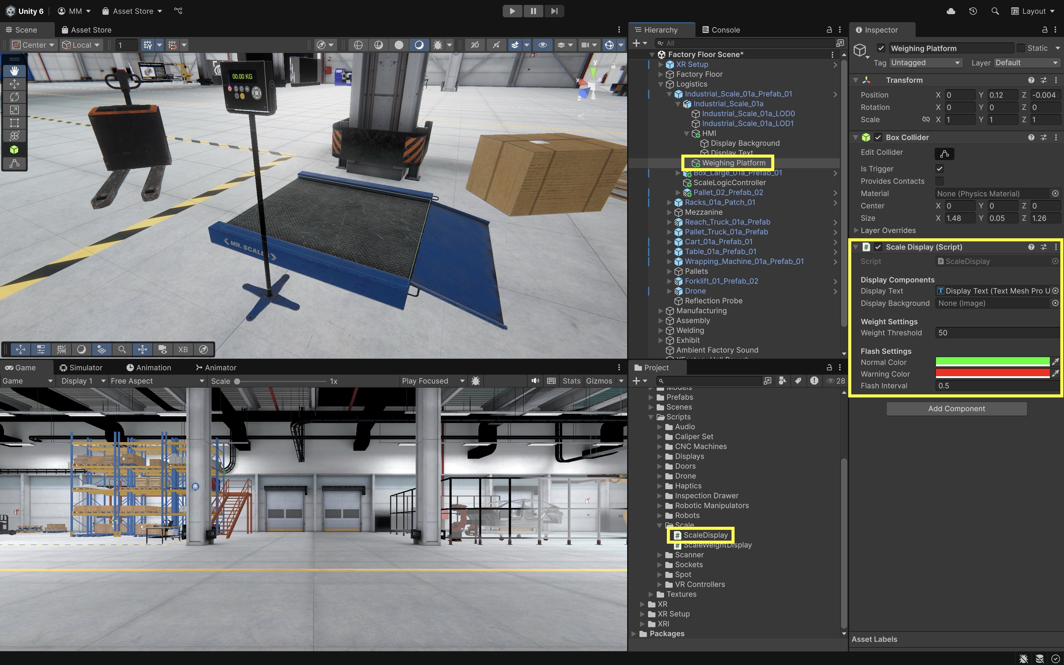
This setup links the virtual scale’s display to the underlying system logic so that UI elements are updated automatically in real time based on physical object interaction.
- Drag the
- Test the Output Behavior:
- Enter Play Mode with Quest Link / Meta Horizon Link or build to Quest for final validation.
- Place several objects with different
Rigidbody.massvalues in the scene. - During play mode, place one or more objects onto the scale surface.
- If the combined mass is below the threshold, the display shows the weight in green.
- If the total exceeds the threshold, the text shows
OVERLOADand the background begins flashing while the text stays readable. - Remove the objects to reset the display, which returns to showing
---. - This is a pure UI as output example. The user does not directly manipulate the interface—the UI passively displays dynamic system feedback, visually communicating the environment’s state.
- Optional Extensions:
- Audio Alert: Add an
AudioSourceto the scale and play an alert sound when overload is detected. You can trigger this in theOnTriggerEnteror within theHandleFlashing()logic. - Animated Background: Animate the
Display Backgroundto pulse or fade during overload using a coroutine or material animation. - Unit Toggle (kg/lb): Extend the display to allow unit switching by integrating a small UI as Input toggle nearby.
- Weight History Log: Add a small scrollable log UI that records the last few weight readings for QA or training purposes.
These enhancements further bridge UI output with additional sensory modalities (audio, motion) and can introduce secondary UI inputs to control display behavior, creating a more complete I/O interaction model.
- Audio Alert: Add an
Best Practices
Designing effective VR user interfaces requires attention to clarity, spatial usability, and immersive interaction. Below are key best practices—grounded in both design theory and real-world implementation using Unity 6.3 LTS and the XR Interaction Toolkit.
- Clarity & Simplicity: Use large, legible fonts like
TextMeshProwith strong contrast (e.g., white on dark panels), and reduce UI clutter by showing only contextually relevant information. High-contrast color schemes and minimal visible elements help focus user attention. Clear and simple UI reduces cognitive load, speeds up decision-making, and prevents user error—especially in time-sensitive or technical tasks. In the CNC HMI panel, use bold text to indicate spindle state, and hide G-code settings when the spindle is running. - Spatial Layout Consistency: Arrange UI elements in realistic, logical groupings that mirror real-world controls, with consistent padding, spacing, and alignment across panels. Use left-aligned or center-aligned layouts consistently within the same interaction context. Consistent layouts make interfaces more predictable and easier to learn, which is crucial for users switching between different stations or tools in a complex VR environment. In XFactory, all large wall displays follow a consistent top-to-bottom flow: title → message → action buttons → secondary links.
- Performance Optimization: Use lightweight materials, throttle frequent updates (e.g., limit chart refreshes to once per second), and avoid excessive animations or high-resolution textures. Rely on event-based scripting instead of polling where possible. Avoid excessive nested canvases. Split static and dynamic UI canvases when needed. Avoid updating many
TextMeshProUGUIfields every frame. Limit transparent overlapping UI graphics because they increase overdraw. Profile UI cost on device, not only in Editor. Final UI performance should be checked on Quest with the target render scale, refresh rate, and scene complexity. - Robust Interaction Feedback: Provide immediate visual (e.g., button glow), audio (click sounds), and haptic (controller vibration) feedback on interactions. Make this feedback consistent across all UI to build trust and improve usability. Immediate feedback reassures users that their actions have registered and helps confirm successful input, reducing frustration and accidental repetitions. Teach pendant buttons highlight and play a subtle tone when pressed, confirming joint jog commands.
- Cross-Device Compatibility: Use
XR Interaction Simulatorfor early layout/debugging, Quest Link / Meta Horizon Link for headset preview, and Android Build and Run for final Quest behavior. Test on other OpenXR-compatible headsets when available. Provide adjustable UI scaling and repositioning for user comfort and accessibility. UseCanvas Scalercarefully for world-space UI. Keep text high resolution and legible in headset. Avoid very small UI hit targets. - Design for Ergonomics: Position UI panels in a comfortable reach zone (typically 0.5m–2m away and 15° below eye level), and use angled or floating panels for wall-mounted interfaces. As a starting point, buttons should be around 2 cm or larger in world units, then verified in headset with the intended interaction method. Avoid placing critical UI at the edge of the user’s field of view. Test seated and standing postures where relevant. The robot teach pendant is angled slightly toward the user and positioned at waist height to reduce arm fatigue.
- Error Recovery and Safety: Include undo, cancel, and reset options for actions that change system state, and confirm critical tasks with dialog prompts. Provide reset/cancel paths. Allow users to safely back out of flows or retry without restarting the scene. In the manufacturing station, the CNC HMI includes a “Reset System” button that first opens a confirmation panel with
ConfirmandCanceloptions. IfConfirmis pressed, a second dialog asks the user to validate the current machine state (e.g., “Is the spindle stopped?”) before finalizing the reset. This prevents unsafe interruptions and gives users a chance to back out safely. If no response is given within 10 seconds, the UI defaults to canceling the operation.
Key Takeaways
- World-space UI needs XR UI Input Module, Tracked Device Graphic Raycaster, and UI-enabled interactors.
- Invisible overlay buttons require Raycast Target and careful alignment with 3D HMI geometry.
- HMIs should gate commands by machine state and expose status through text, color, and interactability.
- Spatial Keyboard suits short entry tasks on TMP fields—not long-form typing.
- Scale displays should label units, throttle updates, and treat Rigidbody.mass as simulation data—not a validated sensor.