D4. Object Attachment in VR

Learning Outcomes
- Explain the concept of sockets for object snapping in XR. Before class, explore how sockets work by relating them to real-world analogies like plugs or mechanical joints.
- Configure a grab-ready object in Unity for socket interaction. For preparation, set up a 3D object with a
Rigidbody, collider, andXR Grab Interactablecomponent, then test its basic grabbing behavior from D3.- Use vector comparisons to validate alignment in snapping interactions. Ahead of the session, review and experiment with
Vector3.Angle()andVector3.Distance()in a script to see how they can enforce positional and rotational constraints.- Distinguish XRI Interaction Layers from Unity physics layers and Tags. Understand how
Interaction Layer Maskfilters socket acceptance separately from physics collider filtering and optional script labels.- Apply socket validation strategies in current XRI. Use XRI Interaction Layers, socket events, and optional select filters or validation scripts to accept/reject parts based on type, distance, orientation, and assembly state.
- Validate engineering socket placement. Confirm that socket placement reflects real-world scale, alignment tolerance, assembly order, and safe task flow.
- Apply best practices for socket-based object attachment. Come ready with one real-world engineering example where precise part alignment is critical, and connect it to XR development considerations.
Sockets
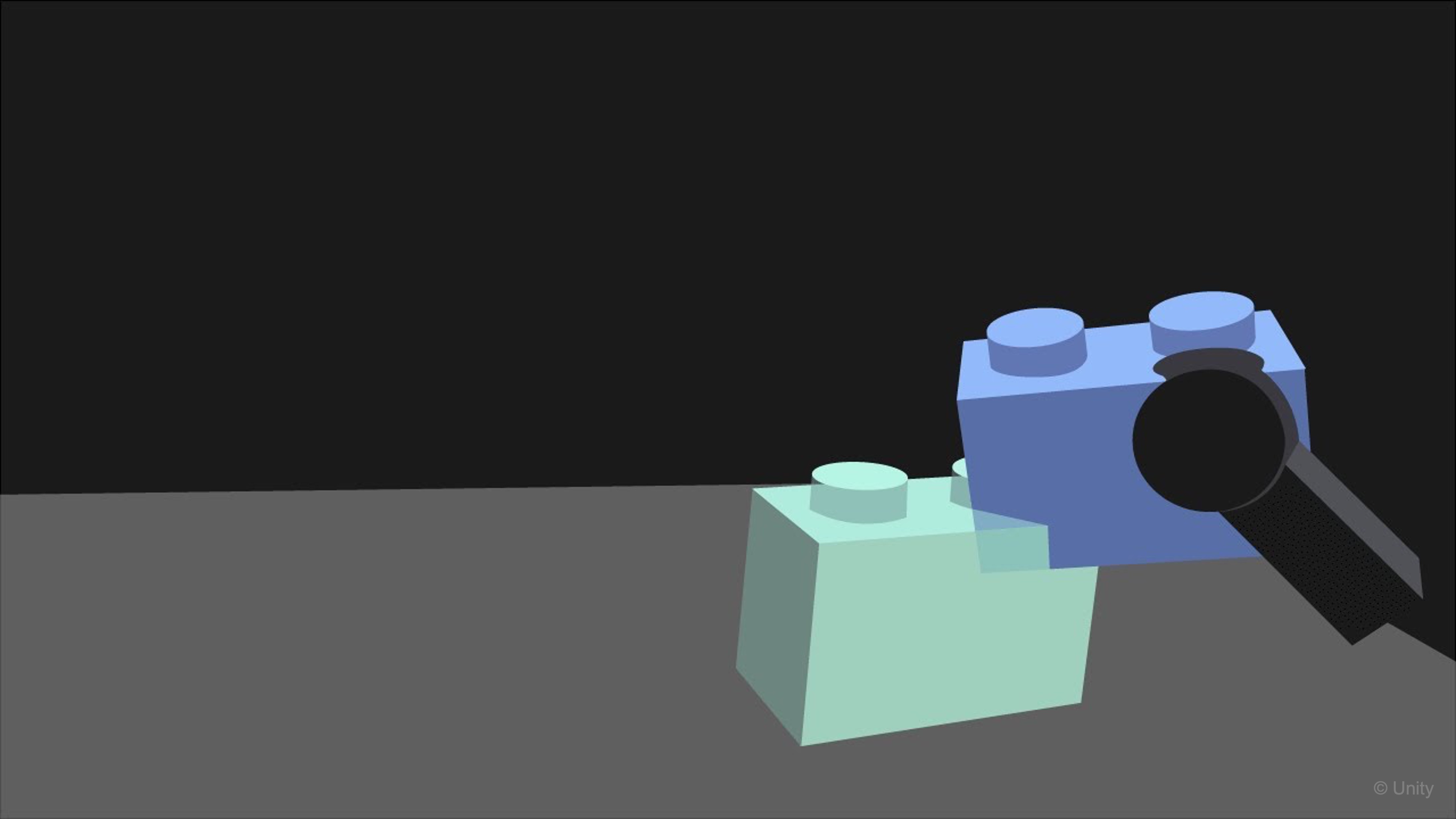
In VR, a socket is a designated area or docking station where an interactable object snaps into a predetermined position and orientation. This ensures objects—like gears in a gearbox or sensors on a panel—align correctly when placed, enhancing user experience through predictable, visually coherent interactions. By using the XR Socket Interactor to define clear attachment points and aligning attach transforms, objects consistently snap into place. Additionally, employing XRI Interaction Layers restricts attachments to the correct objects, further enhancing performance and usability.
In engineering VR, sockets should represent meaningful assembly constraints, not just visual snapping. A tire, lug nut, sensor, or tool should only socket where the real object could plausibly be placed.
Use Cases
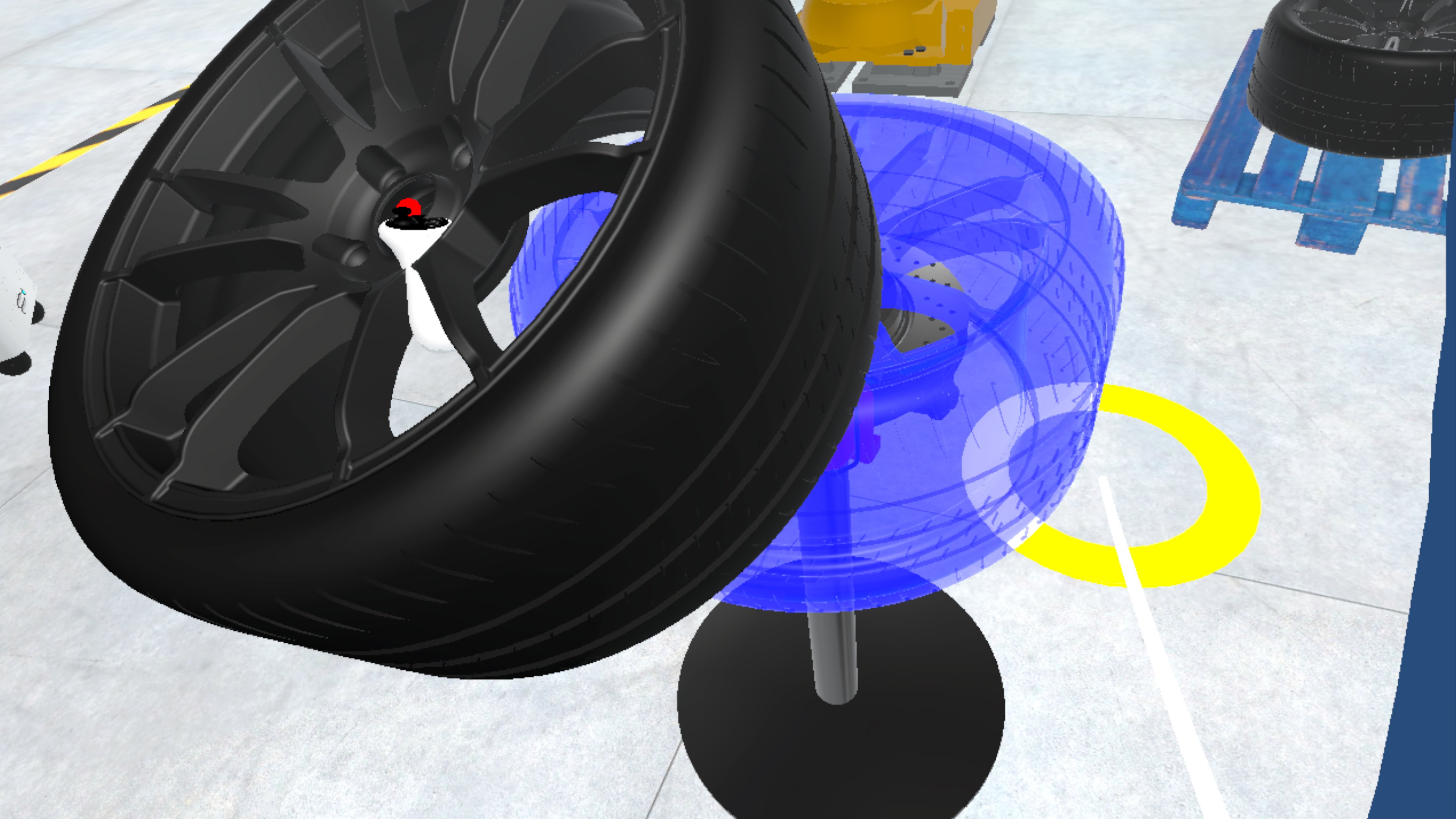
Sockets are a flexible interaction pattern that can be applied across multiple VR domains:
- Engineering & Manufacturing: Assembly training (e.g., attaching machine parts, wiring circuits). Maintenance procedures (e.g., snapping tools back into holders, replacing components).
- Medical Training: Attaching prosthetics or surgical tools to rigs. Snapping medical instruments into sterilization trays or stands.
- Education & Simulation: Teaching physics concepts by building circuits or modular systems. Assembling molecules or models piece by piece.
- Gaming & Entertainment: Weapon or tool customization (e.g., attaching scopes, silencers, or handles). Puzzle mechanics (e.g., fitting shapes into sockets, key-lock systems).
- Architecture & Design: Furniture arrangement with snap-to points. Modular building systems with predefined docking stations.
- Everyday Utilities: Organizing objects on a workstation (e.g., snapping items into holders). Virtual prototyping where parts must consistently align.
Principles
Before diving into technical setup, it is important to understand the principles of socket-based interactions:
- Predictability: Users should always know how and where an object will attach. Clear visual and spatial cues reduce confusion.
- Precision vs. Flexibility: Decide whether sockets should allow loose placement (ease of use) or enforce strict tolerances (engineering realism).
- Feedback & Affordances: Provide visual, audio, or haptic feedback when an object is close to or correctly aligned with a socket.
- One-to-One Relationships: Each socket should be designed for a specific object type (via
Interaction Layers) to avoid unintended snapping. - Performance Considerations: Use minimal colliders and avoid overlapping triggers to maintain smooth interactions.
- Reversibility: Decide whether objects can be removed after being socketed, and under what conditions (e.g., only with a specific tool or action).
XR Socket Interactor
A socket is a snap-to attachment point in XRI: it passively holds eligible interactables in a defined pose, improving alignment, functional realism, and user experience. The XR Socket Interactor component implements this behavior in the scene—not on a controller.
- Snap-to mechanism: Aligns a grabbed or released object to a fixed position and rotation instead of leaving it free-floating.
- Scene/world-space interactor: Lives in the environment (for example, a charging base or assembly fixture), not on the user’s controller.
- Passive detection: Detects eligible interactables that enter its trigger volume; unlike direct interactors, it does not actively reach out to grab objects.
- Trigger collider volume: Defines the region where an interactable can be detected and considered for snapping.
Attach Transform: Optional child transform that sets the exact snap position and orientation.- XFactory example: In the logistics station, the barcode scanner’s charging base uses a socket so the scanner docks in the correct orientation, reinforcing proper handling like real operations.
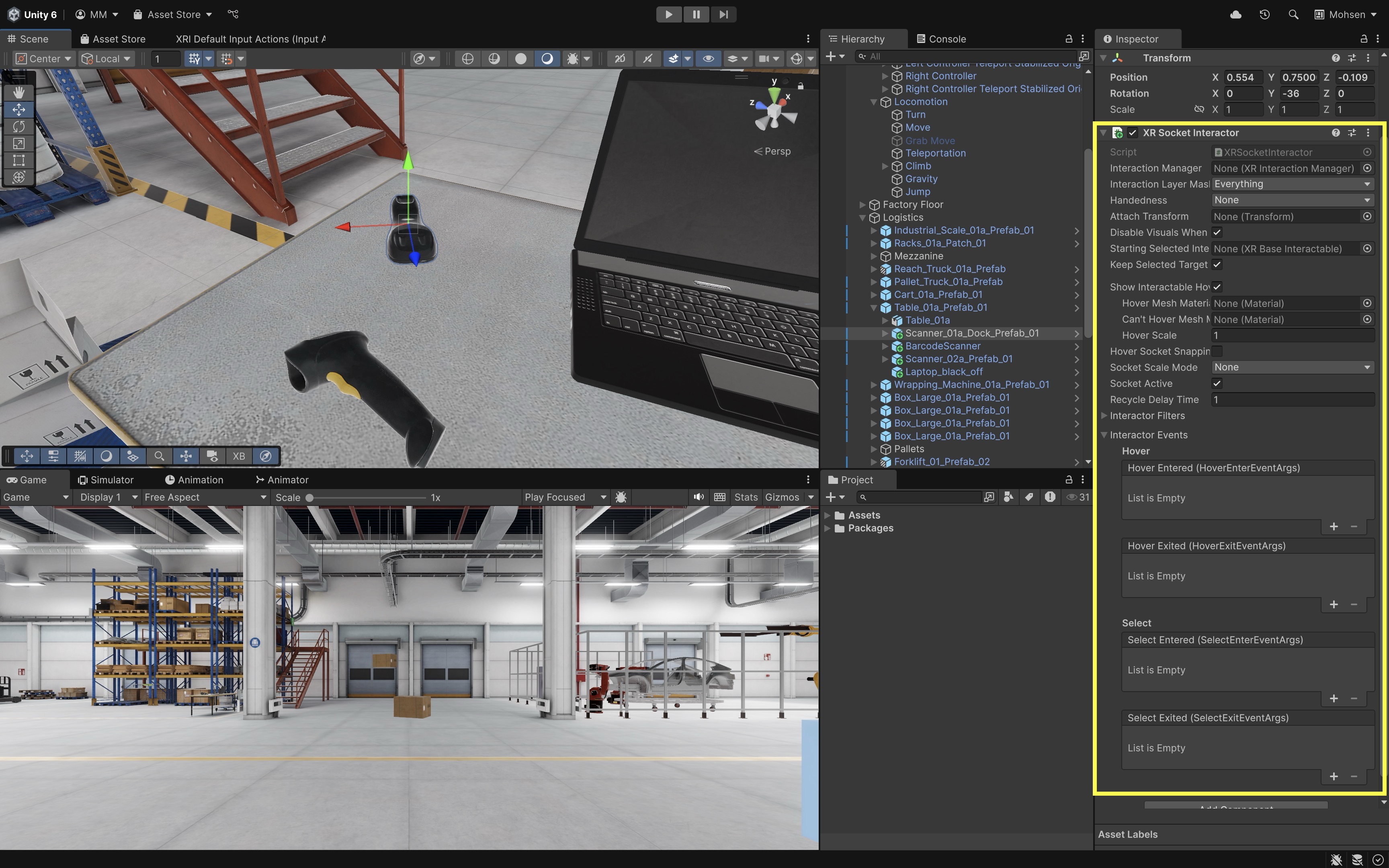
Review this Unity Documentation to learn more about
XR Socket Interactor.
Inspector Properties
When you add an XR Socket Interactor component to a GameObject, you’ll see the following key fields in the Inspector:
Interaction Manager: Reference to theXR Interaction Managerthat coordinates all interactors and interactables. Default:None (XR Interaction Manager)— if left blank, it will attempt to auto-find one in the scene.Interaction Layer Mask: Determines which interactables are allowed to interact with this socket using XRI Interaction Layers. Default:Everything— meaning it will accept all interactables unless filtered.Handedness: Restricts socket usage to a specific controller hand if required. Default:None(no restriction).Attach Transform: A child transform that defines the exact snap position and rotation. This must be set manually for precise alignment.Starting Selected Interactable: Option to auto-attach a specific object when the scene starts. Useful for parts that begin already installed.Keep Selected Target Valid: If enabled, the socket maintains its selection even when the interactable temporarily leaves the socket’s trigger. Use intentionally when objects may move slightly after socketing.Parent Interactable/Auto Find Parent Interactable: Optional settings for nested assemblies where a child socket should coordinate with a parent interactable.Show Interactable Hover Meshes: Toggle to render a hover mesh when an object is near the socket.Hover Mesh Material: Assign a material for valid hover visualization.Can't Hover Mesh Material: Assign a material for invalid hover states.Hover Scale: Adjust scale of the mesh preview during hover.
Hover Socket Snapping: If enabled, the interactable will visually snap into the socket’s attach transform during hover—before being selected.Socket Snapping Radius: Controls how close an interactable must be for hover snapping behavior.Socket Scale Mode: Defines how scaling is applied to objects when attached. Options includeNone,Fixed Scale, andTarget Bounds Size.Fixed Scale/Target Bounds Size: Additional scaling controls depending on the chosenSocket Scale Mode.Socket Active: Toggles the socket’s availability. Useful for dynamically enabling or disabling sockets during gameplay or task steps.Recycle Delay Time: Sets a cooldown before the socket can accept the same interactable again. Useful for preventing rapid attach/detach cycling after removal.Interactor Filters: Allow filtering or conditions for which interactables can hover or be selected.Interactor Events: Unity Events for hover, select enter, and select exit.
Do not enable both hover mesh visuals and hover socket snapping without checking the result; they can visually conflict or create confusing previews.
Events & Extensibility
XR Socket Interactor provides several event hooks for developers to attach custom logic:
-
Interactor Filters: Allow filtering or conditions for which interactables can hover or be selected. -
Interactor Events:Hover Entered (HoverEnterEventArgs): Triggered when an interactable enters the socket’s detection zone.Hover Exited (HoverExitEventArgs): Triggered when it leaves.Select Entered (SelectEnterEventArgs): Triggered when an interactable is successfully socketed.Select Exited (SelectExitEventArgs): Triggered when the interactable is removed from the socket.
All of these event lists are empty by default but can be expanded in the
Inspectorto assign UnityEvents, scripts, or feedback mechanisms.
Attaching Objects using Sockets
Sockets can represent part mounts, assembly points, holders, or loading positions. In this example, we simulate assembling a tire onto a brake caliper and disk, and securing it using five lug nuts, grabbed from a stack box.
Prerequisites
Socket attachment requires a grabbable interactable on the part side and an XR Socket Interactor on the fixture side with a trigger detection volume, an Attach Transform for the snap pose, and compatible XRI Interaction Layers so only the intended object can dock. Before creating sockets for the tire assembly example below, verify:
- Tire/lug nut has
Rigidbody. - Tire/lug nut has valid non-trigger collider(s) for physical interaction.
- Tire/lug nut has
XR Grab Interactable. - Socket has
XR Socket Interactor. - Socket has a trigger collider detection volume.
- Socket and target object share a compatible XRI Interaction Layer.
- Input actions and interactors from D3 are already working.
- If assembly order matters, use socket events to record which sockets are filled and enable the next step only when prerequisites are satisfied.
Prerequisite: This session assumes your D1
XFactoryVRscene includes the complete VR Template XR setup copied fromSampleSceneand that D1–D3 grabbing, input actions, locomotion, and interactors are working in Play Mode.
Implementation
Implementing sockets requires preparing grabbable parts, adding an XR Socket Interactor to each fixture with a trigger volume and Attach Transform, matching interaction layers, and testing snap behavior in Play Mode before wiring events or validation logic.
- Prepare Your Interactable Objects:
- In the
Hierarchy > Assembly, locate your 3D model of theTireon theMetal Table. This object will be socketed (i.e., assembled) onto theTire Stand. - Locate the
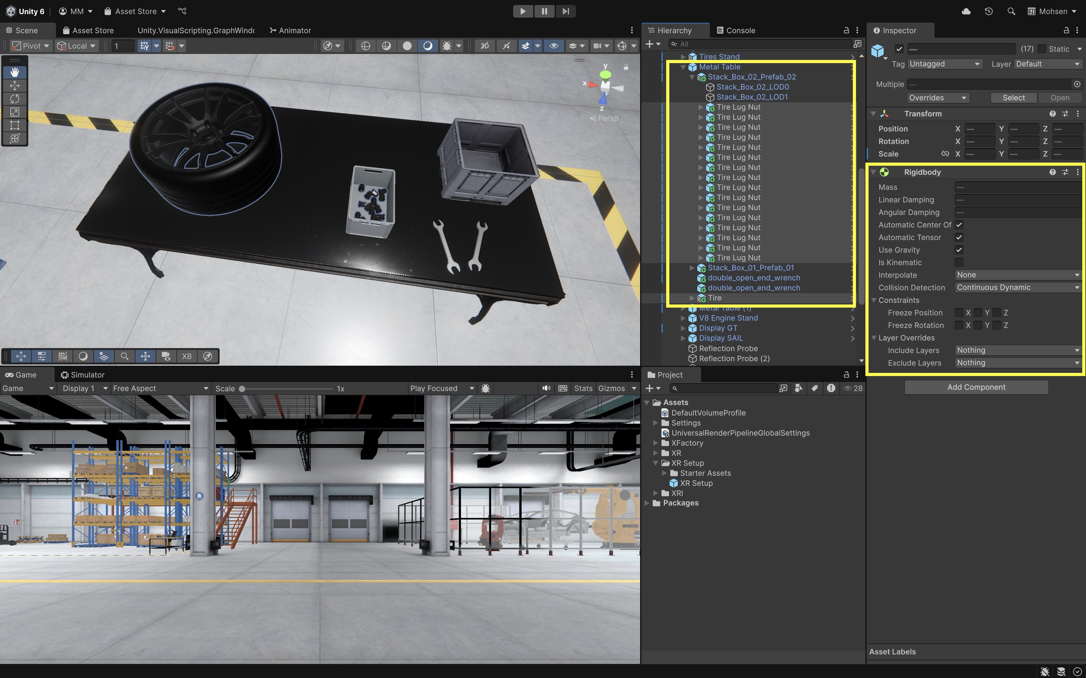
Tire Lug NutGameObjects inside theStack_Box_02_Prefab_02on theMetal Table. These will be picked up and assembled onto theTire. - Interactable objects are those that users can grab, move, and place using XR controllers.
- In the
- Configure Physics:
- Add
Rigidbodycomponents to theTireandTire Lug NutGameObjects. This allows realistic physics and prevents clipping through socket points. - Enable
Use Gravity. - Use
Discretecollision detection for slow, simple objects. UseContinuous Dynamiconly for fast-moving or thrown parts that risk tunneling, because continuous collision detection has a performance cost. - Prefer primitive or compound primitive colliders; use convex mesh colliders only when shape accuracy is necessary.
- Small parts often need simplified colliders, careful mass/drag settings, and tight socket trigger volumes.
- Avoid overlapping colliders at spawn time, and avoid placing socket trigger volumes so close together that one part hovers multiple sockets unintentionally.
- Add
- Make the Objects Grabbable:
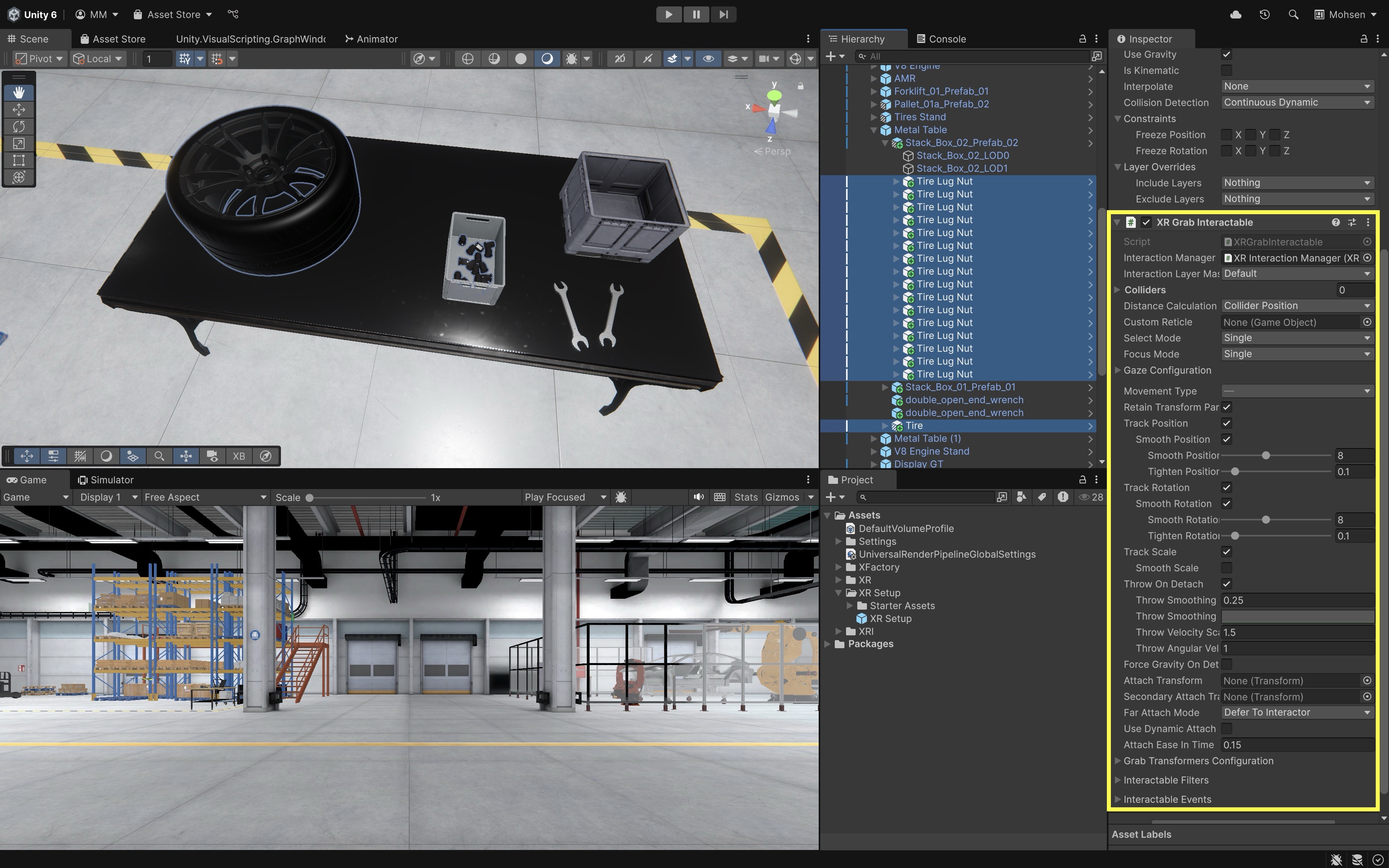
- Add
XR Grab Interactablecomponents to theTireandTire Lug NutGameObjects. - Enable
Smooth PositionandSmooth Rotationfor natural grabbing behavior. - Since the tire is relatively large and heavy, set its
Movement TypetoVelocity Trackingto simulate realistic physics while maintaining responsive control. - Lug nuts are small and lightweight. Therefore,
Movement Type = Kinematicgives more precise control, especially when aligning with small sockets. - Confirm that the models have non-trigger
Collidercomponents.
- Add
- Create the Tire Socket:
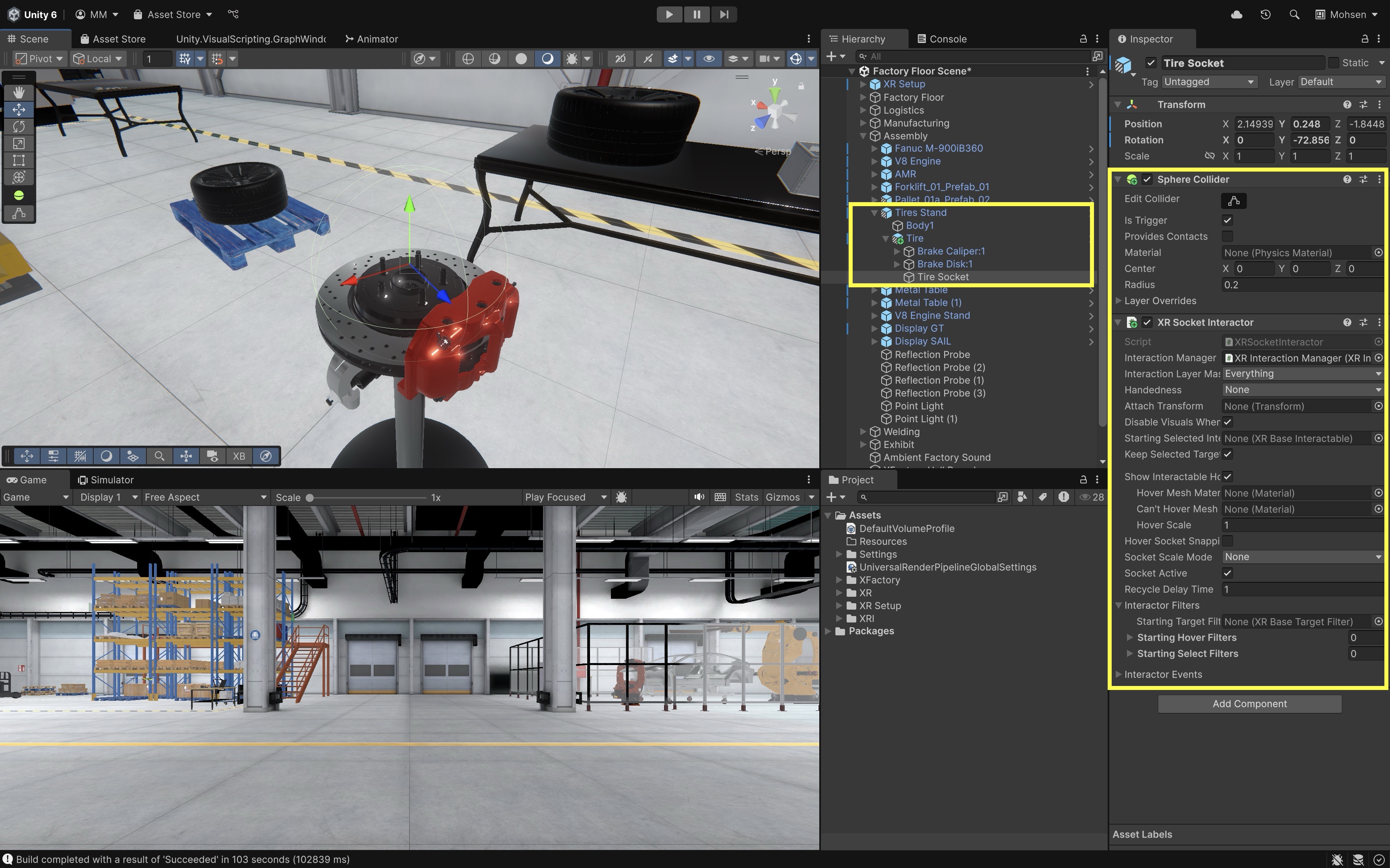
- On the
Tire Stand, create an empty GameObject and name itTire Socket. - Add a
Sphere CollidertoTire Socket. - Adjust the collider radius (e.g.,
0.2) to detect the approaching Tire. Keep trigger zones as small and non-overlapping as practical. - Enable
Is Trigger. - With
Tire Socketselected, add theXR Socket Interactorcomponent.
- On the
- Set Up the Attach Transform:
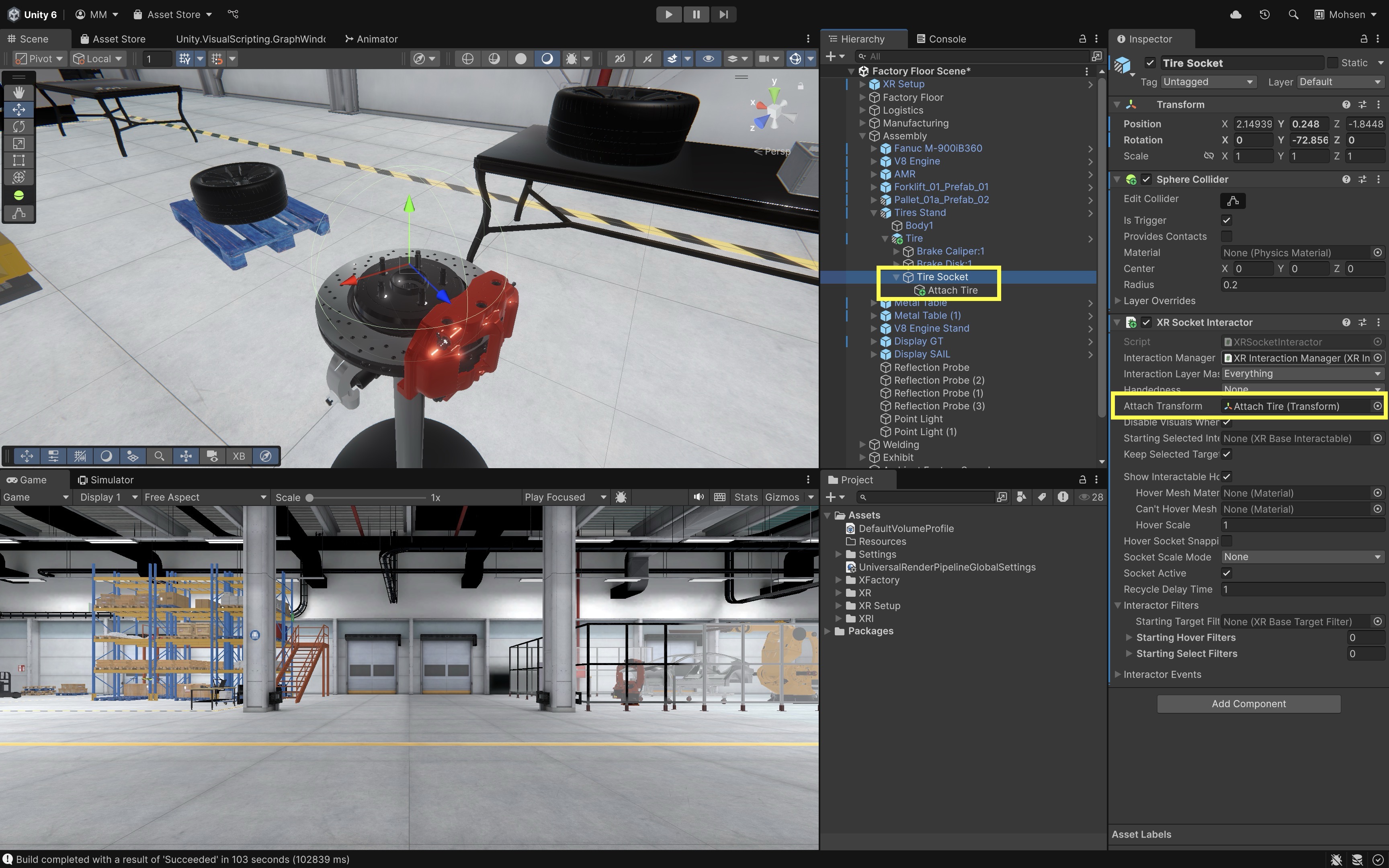
- Create a child GameObject under
Tire Socket, name itAttach Tire. - Temporarily position the tire exactly where it should end up, then create/adjust the socket’s child
Attach Transformto match that final pose. Verify local axes inPivot+Localmode and test in Play Mode. - For the tire, the attach transform should align the wheel axis with the brake disk/hub.
- Assign
Attach Tireto theAttach Transformfield ofXR Socket Interactor.
Tolerance check: A socket that looks correct from one camera angle may still be mechanically wrong. Test alignment from multiple viewpoints and verify the part’s axis, face orientation, and clearance.
- Create a child GameObject under
- Create Lug Nut Sockets:
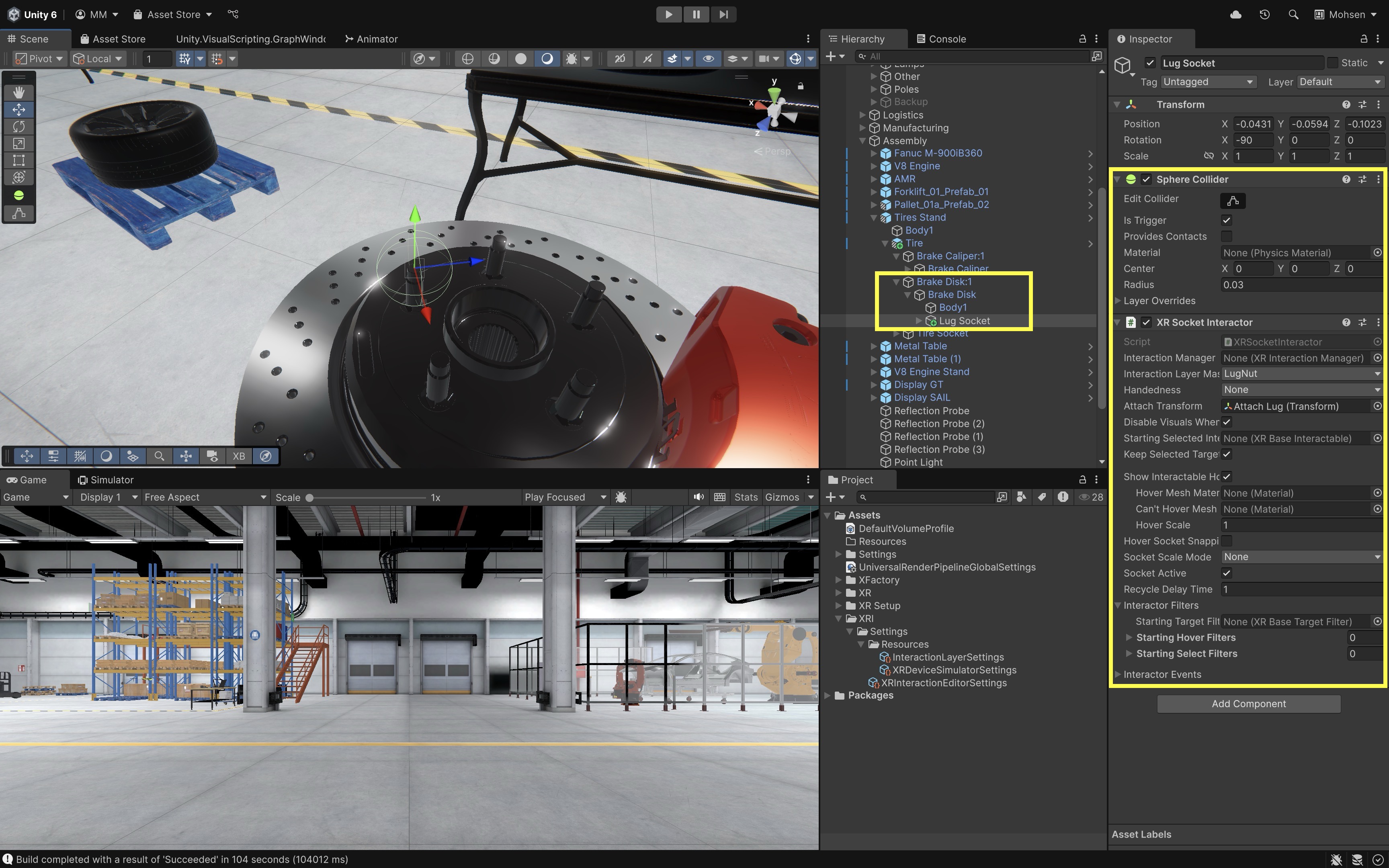
- On the
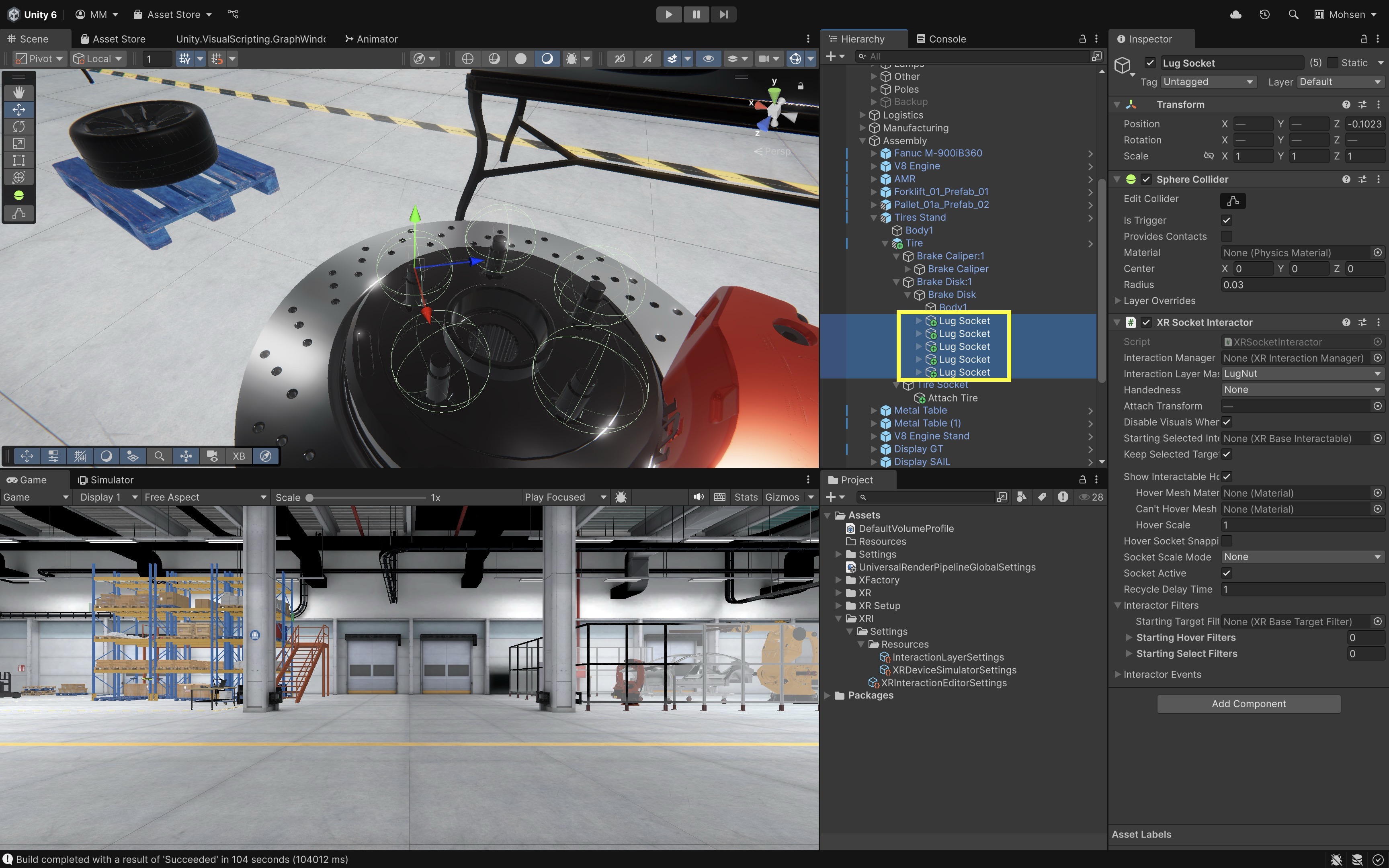
Brake DiskGameObject (a child of theTireunderTire Stand), create an empty GameObject and name itLug Socket. - Position it at the tip of the first screw post where a lug nut will be attached.
- Add a
Sphere CollidertoLug Socket. - Enable
Is Trigger. - Adjust the radius (e.g.,
0.03–0.05) to create a small, accurate detection zone. - Add the
XR Socket Interactorcomponent toLug Socket. - Create or choose an XRI Interaction Layer such as
Tire,LugNut, orEnginePart, then assign that layer in both the socket’sInteraction Layer Maskand the interactable’sInteraction Layer Mask. - Create a child GameObject under
Lug Socketand name itAttach Lug. - Temporarily position the lug nut exactly where it should end up, then adjust
Attach Lugto match that final pose. For lug nuts, the attach transform should align the nut’s axis with the screw post. - Assign
Attach Lugto theAttach Transformfield of the socket.
Common mistake: XRI Interaction Layers, Unity physics Layers, and Tags are three different systems.
Interaction Layer Maskcontrols which XRI interactors/interactables can interact. Unity physics Layers control collider/caster filtering. Tags are simple labels for scripts and do not automatically affect socket acceptance.Make sure all
Lug Nutobjects and lug sockets share the same XRI Interaction Layer (for example,LugNut) so lug sockets detect lug nuts without interfering with the tire socket. Tags can be used in optional custom scripts, but they are not the primary filtering workflow. - On the
- Duplicate for Remaining Lug Nut Positions:
- In the
Hierarchy, duplicateLug Socketfour times. - Reposition each socket at the tip of its corresponding screw post.
- This method ensures consistent and accurate socket configuration across all lug nut positions while saving setup time.
- In the
- Add Hover Audio Feedback (Interactor Event):
- In your project, create a
HoverSoundPlayer.csscript:
using UnityEngine; using UnityEngine.XR.Interaction.Toolkit; public class HoverSoundPlayer : MonoBehaviour { [SerializeField] private AudioSource hoverAudio; // Called by XR Socket Interactor → Interactor Events → Hover Entered public void PlayHoverSound(HoverEnterEventArgs args) { if (hoverAudio != null) hoverAudio.Play(); } }- Create an
Empty GameObjectin your scene, name itHoverSoundManager. Add theHoverSoundPlayercomponent to it. - Add (or reference) an
AudioSourcewith your hover sound and drag it into theHover Audiofield of the script. - Select a
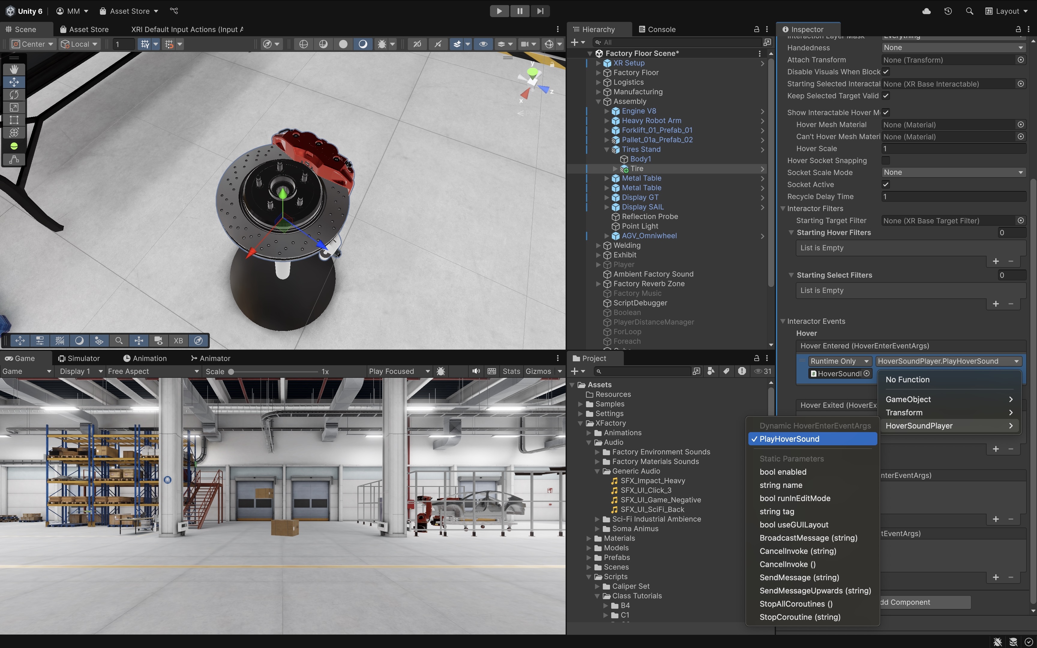
XR Socket Interactor(for example,Tire Socketor eachLug Socket). - In the
Inspector, expandInteractor Events → Hover → Hover Entered. - Click
+, drag theHoverSoundManagerGameObject into the object field. - From the function dropdown, choose:
HoverSoundPlayer → PlayHoverSound(HoverEnterEventArgs).
You can reuse the same
HoverSoundManageracross all sockets to keep setup simple. For hover haptics, preferSimple Haptic Feedbackwith aHaptic Impulse Playeron the interactor when possible. Use scripts only when feedback must depend on socket state, part type, or validation result.For production feedback, use a spatial
AudioSourceon or near the socket so volume, spatial blend, mixer routing, and distance falloff are controllable. - In your project, create a
- Deploy and Test:
- Enter Play Mode with the XR Interaction Simulator or Quest Link / Meta Horizon Link (Windows) for rapid preview.
- Build and run to Quest through the Android/Meta Quest pipeline for final standalone validation.
- You can experience a complete tire assembly sequence.
- When the part hovers over the socket, you’ll hear the sound play.
Snapping with Constraints
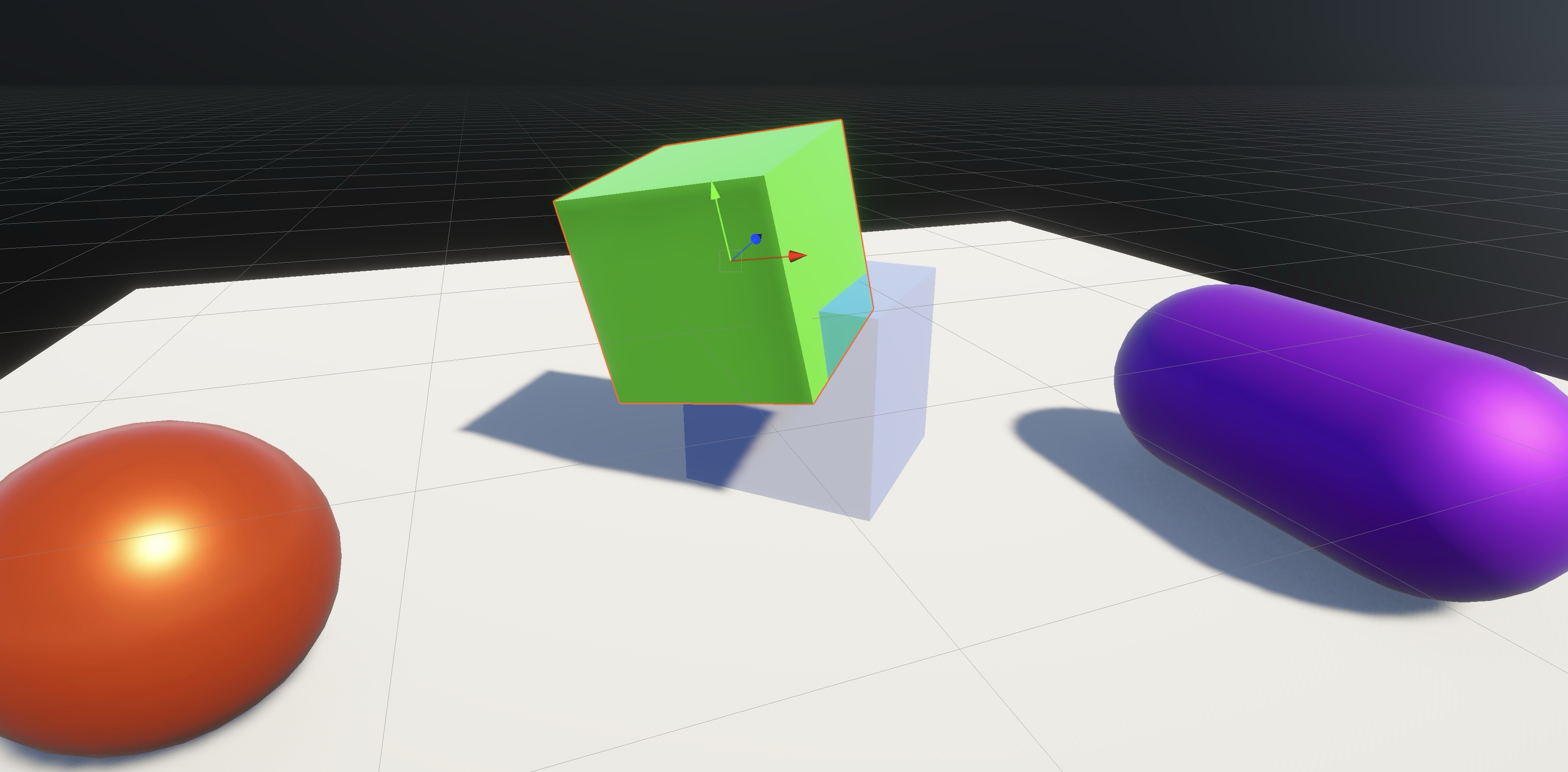
Basic XR Socket Interactor snapping is enough for demos, but engineering and training tasks often require parts to meet real assembly tolerances—such as tire/lug nut placement or V8 engine components—before they are accepted.
- Custom alignment rules: Define the rotational and positional limits a part must meet before the socket accepts it.
- Placement validation: Use vector math and distance checks (for example,
Vector3.Angle()and position offset) to confirm the part is within tolerance. - Rejection feedback: Provide haptics and audio when a part is close but not correctly aligned, so users know the snap was rejected.
- Engineering verification: Confirm units, scale, axis alignment, clearance, tolerance thresholds, and assembly order before treating the result as valid for training or design review.
- Training intent: Sockets should reinforce correct procedure and mechanical realism, not simply make parts easier to place.
- Visual caution: A snap can look correct in VR even when the part is mis-scaled, misaligned, or mechanically impossible—validate behavior in headset, not only by appearance.
For simple tutorials, validating in
Select Enteredand then canceling/rejecting can demonstrate the idea. For cleaner production behavior, use XRI Interaction Layers for type filtering and customIXRSelectFilterlogic or interactor filters to prevent invalid selection before the part snaps. A customIXRSelectFilteris useful for strict engineering assembly validation, but the event-based examples below are easier for a first socket lesson.
Angle Tolerances
Vector math allows you to check angle tolerances. For a lug nut, compare the part’s intended forward/up axis to the socket attach transform’s corresponding axis, not always to Vector3.up. Use Vector3.Angle(partAxis, attachTransform.up) or attachTransform.forward, depending on how the model’s local axes represent insertion direction:
float angle = Vector3.Angle(part.up, attachTransform.up);
if (angle > maxAngleDeviation)
{
    // Reject the snap.
}
In XFactory’s assembly station, validate that a lug nut is aligned correctly before snapping to the brake disk. Get the lug nut’s intended axis, compare it to the socket attach transform axis, use
Vector3.Angle()to measure the deviation, and accept the snap only if within a defined range (e.g., ±10°).
Distance
You can prevent snapping if a part is not close enough to its intended attach point, ensuring users move the part with adequate precision. Compare distance in world space to the socket attach transform:
float distance = Vector3.Distance(part.position, attachTransform.position);
if (distance > maxSnapDistance)
{
    // Reject the snap.
}
For small parts, distance thresholds should be in meters and should reflect realistic task tolerance. A value like
0.15 mmay be too generous for lug nuts; use smaller thresholds for precision assemblies. Tune tolerance values in headset and validate them against the engineering task.
Feedback
When misalignment is detected during socket interaction, it is important to give the user clear and immediate feedback. This can include audio cues (e.g., error sounds), haptic feedback via the VR controllers, visual cues or messages, or rejection of the snap, allowing retry or resetting the part’s position. The combined validator below is the practical version for angle and distance checks together. For hover/select haptics, prefer Simple Haptic Feedback with a Haptic Impulse Player on the interactor when possible. Attach PartSnapValidator.cs to any socket that requires combined angle and distance validation. Make sure to assign the correct Attach Transform (child GameObject) in the Inspector. Optionally, assign an AudioSource to play error feedback when misalignment is detected. If this script does not compile, verify the installed XR Interaction Toolkit package version, namespaces, and cancellation APIs before changing the validation logic.
using UnityEngine;
using UnityEngine.XR.Interaction.Toolkit;
using UnityEngine.XR.Interaction.Toolkit.Inputs.Haptics;
using UnityEngine.XR.Interaction.Toolkit.Interactables;
using UnityEngine.XR.Interaction.Toolkit.Interactors;

public class PartSnapValidator : MonoBehaviour
{
    [SerializeField] private Transform attachTransform;
    [SerializeField] private float maxAngle = 10f;
    [SerializeField] private float maxDistance = 0.05f;
    [SerializeField] private AudioSource errorAudio;

    private XRSocketInteractor socket;

    void OnEnable()
    {
        if (!TryGetComponent(out socket) || socket == null)
            return;

        socket.selectEntered.AddListener(ValidatePart);
    }

    void OnDisable()
    {
        if (socket != null)
            socket.selectEntered.RemoveListener(ValidatePart);
    }

    void ValidatePart(SelectEnterEventArgs args)
    {
        if (args.interactableObject == null || attachTransform == null || socket.interactionManager == null)
            return;

        Transform part = args.interactableObject.transform;
        Vector3 partAxis = part.up;
        float angle = Vector3.Angle(partAxis, attachTransform.up);
        float distance = Vector3.Distance(part.position, attachTransform.position);

        if (angle > maxAngle || distance > maxDistance)
            RejectPart(args);
    }

    void RejectPart(SelectEnterEventArgs args)
    {
        IXRSelectInteractable part = args.interactableObject;

        // Cancel the invalid socket-part selection for tutorial simplicity after Select Entered.
        if (args.interactorObject != null)
            socket.interactionManager.SelectCancel(args.interactorObject, part);

        if (errorAudio != null)
            errorAudio.Play();

        if (args.interactorObject is Component interactorComponent)
        {
            var hapticPlayer = interactorComponent.GetComponentInParent<HapticImpulsePlayer>();
            if (hapticPlayer != null)
                hapticPlayer.SendHapticImpulse(0.7f, 0.2f);
        }

        // Haptic support depends on controller and runtime support.
        Debug.Log("Part rejected: not aligned or positioned correctly.");
    }
}
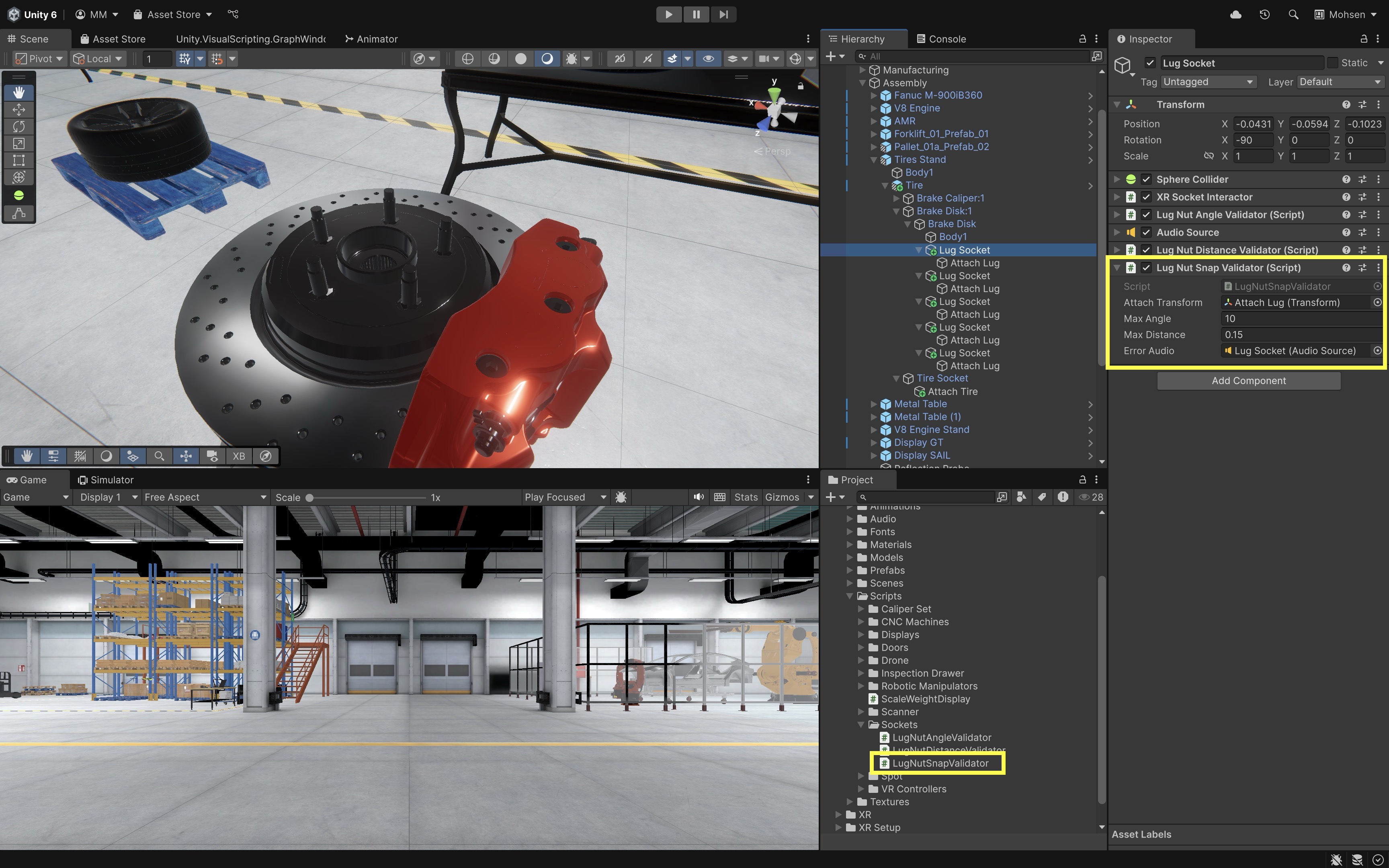
For production assembly validation, prefer pre-select filtering with an
IXRSelectFilterwhen you want to prevent invalid snapping before the object visually attaches.
Best Practices
The following guidance will help ensure reliable, realistic, and maintainable socket-based interactions in your XR projects—particularly when assembling complex objects in XFactory. Use it both while building sockets and as a verification pass before moving on.
- Attach Transforms: Ensure that the local axes of the
Attach Transformmatch the intended orientation of the attached object. Test alignment from multiple viewpoints, not just one camera angle. In XFactory, when inserting a piston into a V8 engine block, a misaligned attach transform can cause the piston to appear rotated or offset. - Trigger Colliders: Always use the smallest collider radius that still detects the intended object. Prefer
Sphere CollidersorBox Collidersthat tightly match socket volume. Set the collider asIs Triggerto detect entry without physical collisions. Keep socket trigger colliders small and non-overlapping so one part does not hover multiple sockets at once. - Interaction Layers: Use XRI Interaction Layers for broad object categories (e.g.,
Pistons,Tires,LugNut,Tools). Assign both interactable objects and sockets to the correct layers via theInteraction Layer Mask. Use filters or scripts for fine-grained validation. Verify that each socket accepts only its intended part type—for example, a tire socket should not accept lug nuts, and lug sockets should not accept the tire or unrelated tools. - Alignment Validation: For realistic mechanical constraints, validate position and orientation before accepting a snap. Use
Vector3.Angle()for angular checks andVector3.Distance()for proximity. Reject poorly aligned parts and provide user feedback (e.g., audio, haptics). Confirm that invalid angle/distance is rejected with clear feedback in headset. - Improper Object Snapping: If a part snaps incorrectly, check that the
Attach Transformis positioned, rotated, and assigned in theXR Socket Interactorcomponent. Use debugging tools (e.g.,Debug.DrawRay()) to visualize socket orientation in theSceneview. - Physics Behavior: Assign
Rigidbodycomponents and valid non-trigger colliders to grabbable objects. UseDiscretecollision detection for simple slow objects; useContinuous Dynamicselectively for fast-moving or thrown parts. Grabbable or socketed parts should not be marked static. Check for jitter caused by overlapping colliders at spawn time or incorrectmass/dragsettings. - Socket lifecycle controls: Use
Socket Activeto enable/disable sockets by task step. UseRecycle Delay Timeto prevent rapid re-socketing loops. UseStarting Selected Interactablefor parts that begin already installed. UseKeep Selected Target Validintentionally when slight post-snap movement is expected. Decide whether socketed parts can be removed according to the lesson design. - Feedback and task flow: Use hover feedback sparingly so dense assemblies do not become noisy. Confirm hover mesh/preview appears only for valid objects. Prefer
Simple Haptic Feedbackwith aHaptic Impulse Playerfor common cases. - Prefabs and reuse: Keep reusable sockets and parts as prefabs so tire, lug nut, piston, scanner, and engine assembly setups stay consistent across XFactory stations.
- Custom Logic: Pair sockets with scripts that validate geometry, check assembly order, and give meaningful feedback when proximity-based attachment alone is not enough. Check each socket’s selection state through the current XRI API rather than relying on older property names such as
selectTarget. - Testing workflow: Verify setup in Play Mode with the XR Interaction Simulator or Quest Link / Meta Horizon Link (Windows), then validate final standalone behavior with an Android build-to-device test on Quest. Confirm tracking, haptics, performance, and thermal behavior on device—not only in the Editor.
Key Takeaways
- XR Socket Interactor defines snap targets; grabbed parts need correct physics and interactable setup.
- Attach transforms, interaction layers, and socket sizing prevent wrong placements and accidental snaps.
- Engineering validation (alignment, distance, orientation) can reject incorrect parts before they lock in.
- Socket completion feedback should come from the socket event, not just generic release elsewhere.
- Organized prefabs, assembly order, and Quest testing make socket workflows maintainable at scale.