D2. Spatial Navigation in VR
Learning Outcomes
- Apply VR coordinate systems. Practice Global vs. Local gizmos, test Unity’s left-handed axes, and compare world vs. local transforms. Review personal space zones to trigger cues when proximity boundaries are crossed.
- Continue from the D1 VR scene. Work in your
XFactoryVRscene with the XR setup copied from the VR TemplateSampleScene; verify OpenXR, input actions, and interaction profiles from D1.- Implement locomotion. Configure the copied
XR Origin (XR Rig)with a Locomotion Mediator and XR Body Transformer; test teleportation, snap turn, continuous turn, and continuous move while avoiding conflicting locomotion inputs—especially by using only one turn style at a time.- Optimize for performance. Use 90 FPS as a common comfort target when appropriate, but treat performance budgets as device- and scene-dependent based on headset, refresh-rate setting, render scale, scene complexity, and course hardware. Batch static objects, reduce poly/texture costs, limit effects, and use MSAA where supported in URP.
Spatial Awareness
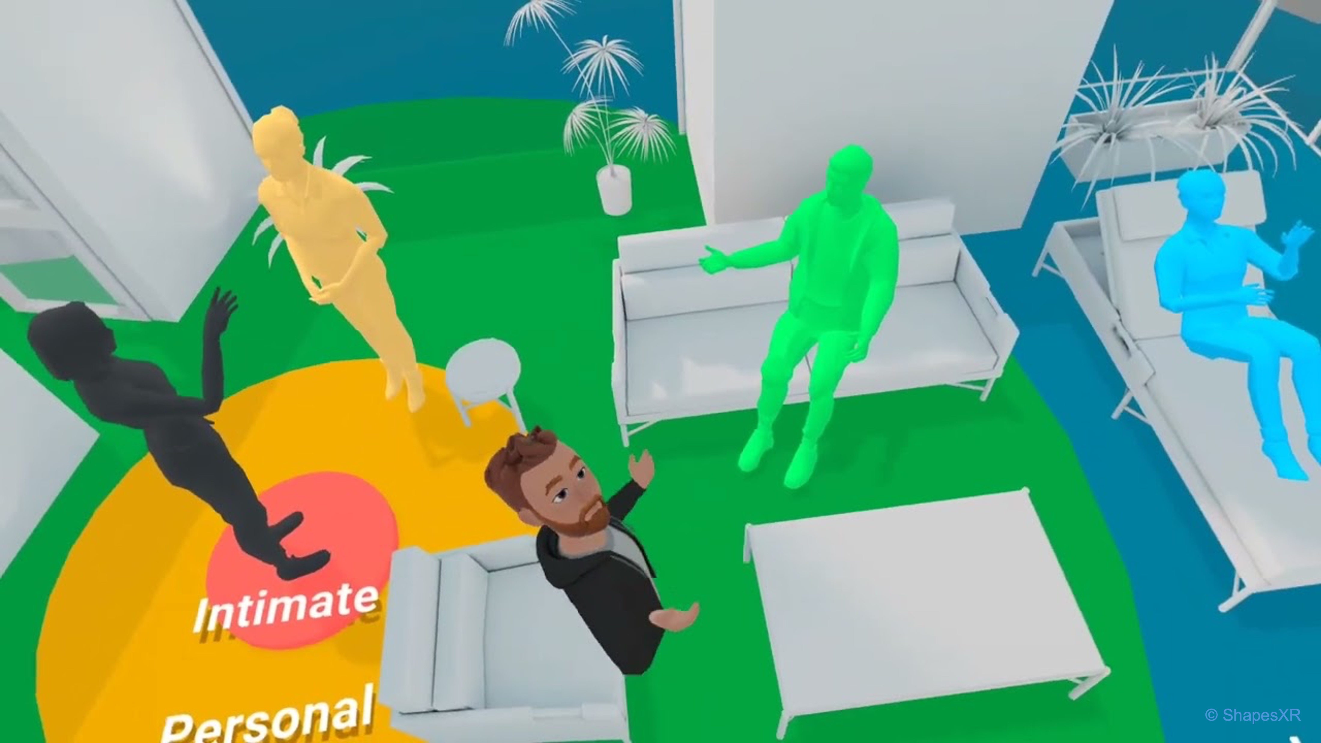
Spatial awareness in VR refers to the user’s ability to perceive and understand the positions, orientations, and relationships of objects—and of themselves—within a 3D virtual environment. This awareness is driven by multisensory input, including visual, auditory, and haptic cues, and is enhanced by technologies such as head tracking, hand/controller tracking, spatialized sound, and real-time feedback. To support this immersive perception, VR environments rely on a set of coordinate systems—including world, local, and camera-relative frames of reference—that define how objects are positioned, moved, and interacted with. Understanding these coordinate systems is fundamental to designing VR experiences that feel spatially coherent, responsive, and believable.
Coordinate Systems in VR
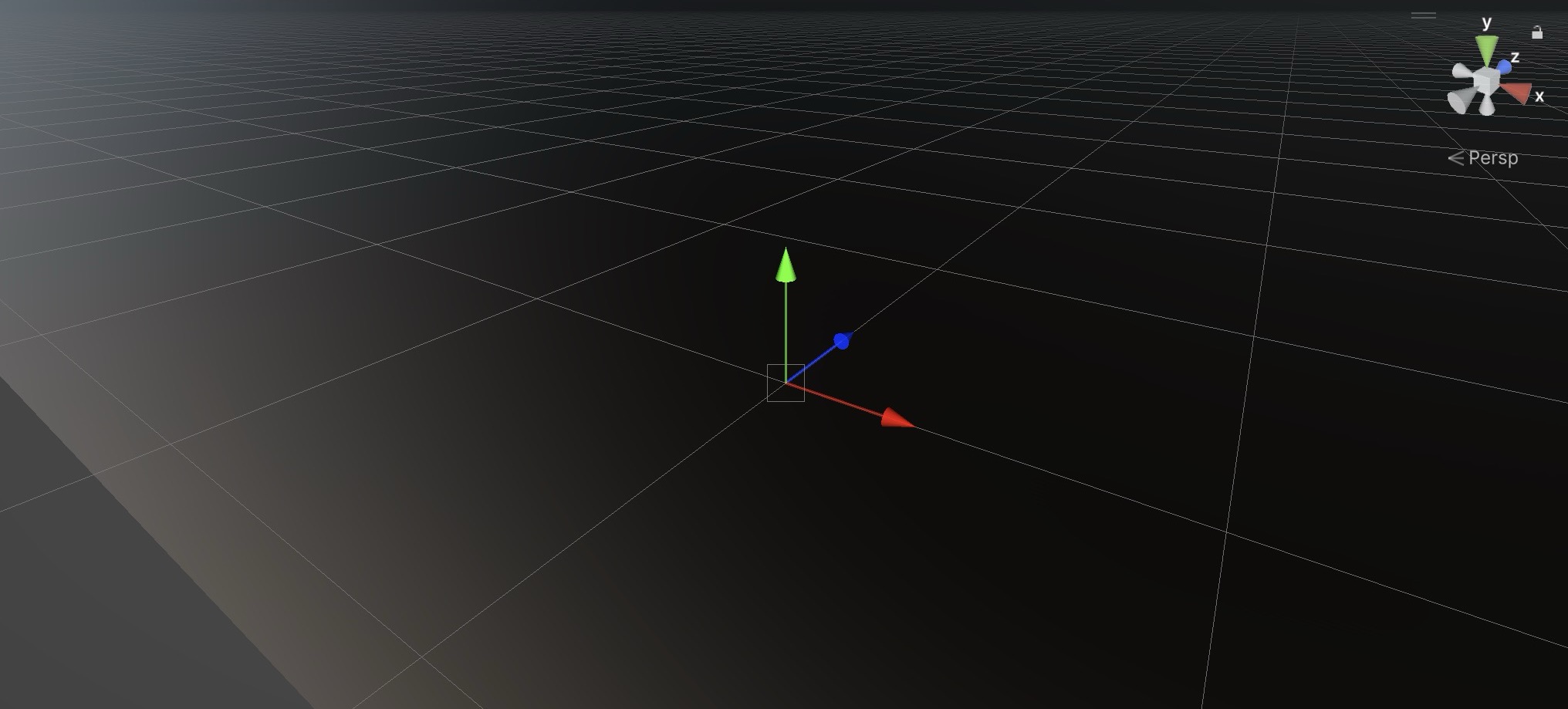
In VR development, coordinate systems provide the framework for positioning, orienting, and scaling every element in your virtual world. A deep understanding of coordinate systems in VR is critical for creating immersive and technically robust experiences. By mastering the interplay between world, local, and view coordinate systems—and understanding how Unity’s left-handed system operates—you can ensure that every object in your virtual world is placed accurately and behaves consistently. Coordinate systems are essential for ensuring that virtual objects maintain their intended spatial relationships as the user moves. Accurate positioning and orientation of objects help the user feel grounded within a believable, interactive space, and proper management of coordinate systems minimizes errors like drift or scaling mismatches that can break immersion. Unity uses a left-handed coordinate system for its 3D space. Here’s a breakdown of how the axes are oriented:
X-axis: Represents horizontal movement, with the positive direction typically pointing to the right.Y-axis: Represents vertical movement, with the positive direction pointing upwards.Z-axis: Represents depth, with the positive direction typically pointing forward (out of the screen) in Unity’s left-handed coordinate system.
Left-handed coordinate system uses the left hand for the axis orientation. Here, the positive
Zaxis points away from the viewer. Unity uses a left-handed system for its 3D world. This means when you specify a position like(X, Y, Z), theZvalue increases as objects move away from the camera. Knowing your system’s handedness helps in importing assets, adjusting lighting, and ensuring proper camera behavior.
World Coordinate System
The world coordinate system is the global reference frame for the entire scene. It defines a fixed, universal orientation across the entire Unity environment. The world origin (0, 0, 0) is typically set near the player’s starting point or a defined central location in the virtual factory. This origin serves as the anchor point from which all objects’ positions, directions, and distances are ultimately measured. The world coordinate system uses a left-handed axis convention in Unity, where:
- Positive
Xpoints right - Positive
Ypoints up - Positive
Zpoints forward (out of the screen)
These fixed world directions remain constant, regardless of an object’s orientation or parent-child relationships. This system ensures a consistent and shared spatial layout, enabling accurate placement, navigation, and alignment of objects throughout the scene.
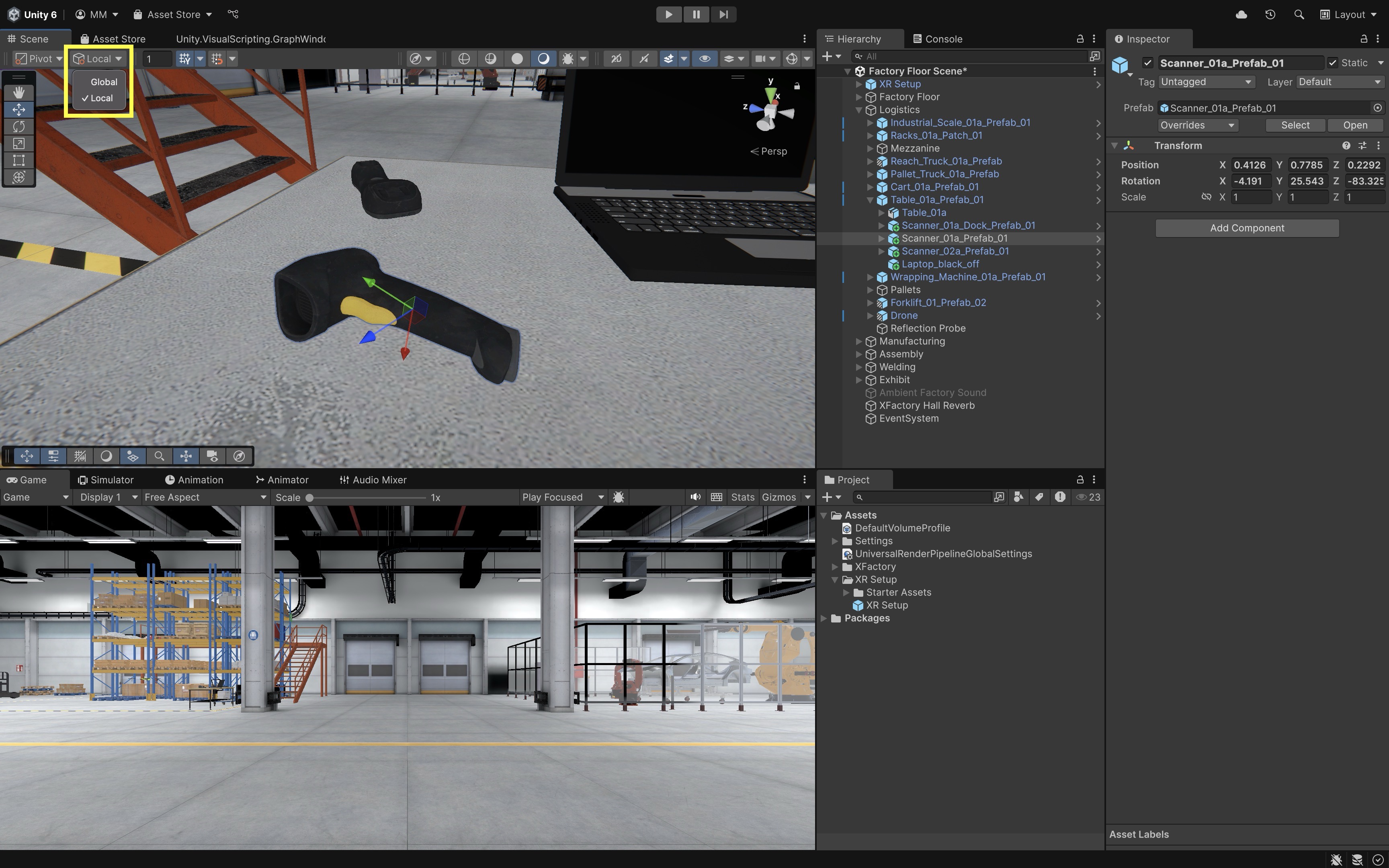
In the logistics station, select a drone or scanner. Toggle between
GlobalandLocalhandle modes in the Unity toolbar, then move the object using theMovetool (W). InGlobalmode, the arrows follow the fixed world axes (X: red,Y: green,Z: blue), while inLocalmode, they align to the object’s current rotation. This clearly shows how world and local directions differ.
Local Coordinate System
Every GameObject in Unity also has a local coordinate system—its own frame of reference that travels and rotates with it. This system defines the object’s orientation and position relative to itself, rather than the world. Local axes are especially important when dealing with hierarchical relationships, such as child objects attached to a parent, or when animating complex, articulated mechanisms. In local space:
- The
Xaxis represents the object’s right direction - The
Yaxis represents the object’s up direction - The
Zaxis represents the object’s forward direction
These directions are influenced by the object’s rotation and are used in calculations like local movement, local rotation, and parenting. This makes local coordinates essential for precise control of movement and orientation, particularly in robotic arms, vehicles, characters, and modular machines. Note that Unity units are treated as meters in typical VR workflows.
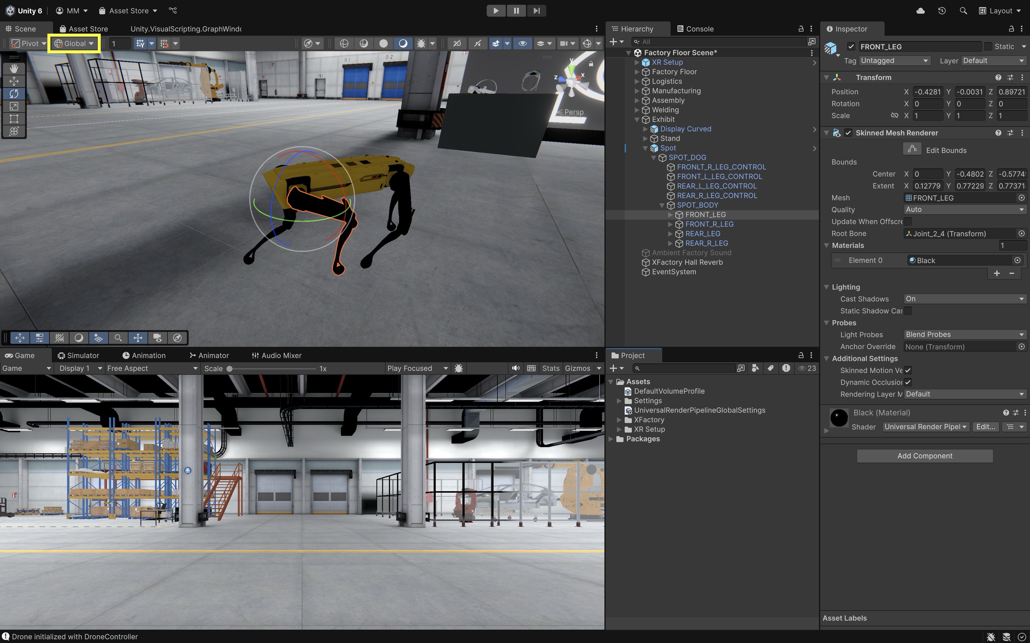
In the exhibit station, select one of the leg joints on the quadruped robot (
Spot). Use theRotatetool (E) and toggle betweenLocalandGlobalmodes. When you rotate the joint inLocalmode, the rotation follows the natural direction of the joint, consistent with the leg’s intended movement. InGlobalmode, the gizmo remains aligned with the world axes, making the rotation feel off or unnatural for articulated motion.
Camera Coordinate System
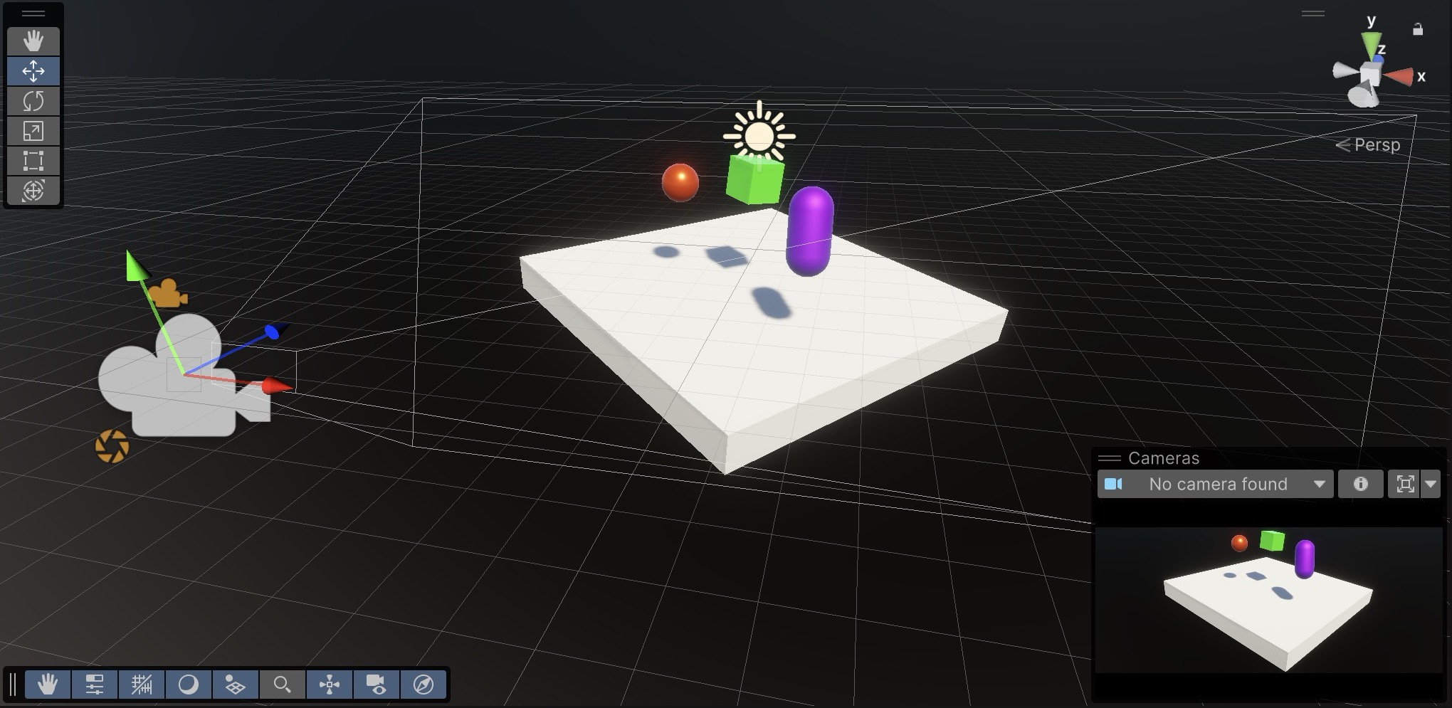
The camera (or headset) coordinate system is dynamic—it updates in real time with the user’s head position and orientation. In XR, the camera becomes the user’s point of view, serving as the basis for rendering the scene and positioning UI or interactive elements. Key spatial behaviors and scenarios include:
- World-Locked Content: Objects are fixed in the environment and do not follow the user (i.e., the camera). Ideal for props, machines, landmarks, or spatial UI that needs to stay consistent as the user moves around. For example, the CNC machines in the manufacturing station remain anchored regardless of user movement.
- Head-Locked (View-Fixed) Content: Objects move with the user’s head, maintaining a fixed offset in view space. Common for HUDs, notifications, or tooltips. Use sparingly to avoid motion sickness or visual overload.
- Seated Experiences: The user is expected to stay seated. The world origin is usually aligned with the user’s initial head position, making camera-relative offsets predictable in limited physical space. This is suitable for simulations or control panels where physical movement is minimal.
- Standing Experiences: The user stands and may walk or move within a physical play area. The world origin is aligned with the floor plane, and content should be positioned with physical scale and posture in mind. This is useful for interactive demos or exploring full-scale scenes like XFactory’s exhibit zone.
- Hybrid Experiences: Some setups blend seated and standing interactions—for example, a user may stand to explore content but sit to operate a virtual machine. In XFactory’s exhibit station, users may stand to explore AR/VR displays but sit for testing simulations, requiring flexible origin handling.
Drifts may happen as a result of gradual inaccuracies in the system’s understanding of position over time. Techniques such as periodic re-centering of the world origin help minimize drift. Regular calibration ensures that long-duration VR sessions maintain positional accuracy and prevent the feeling of disorientation.
Proxemics in VR
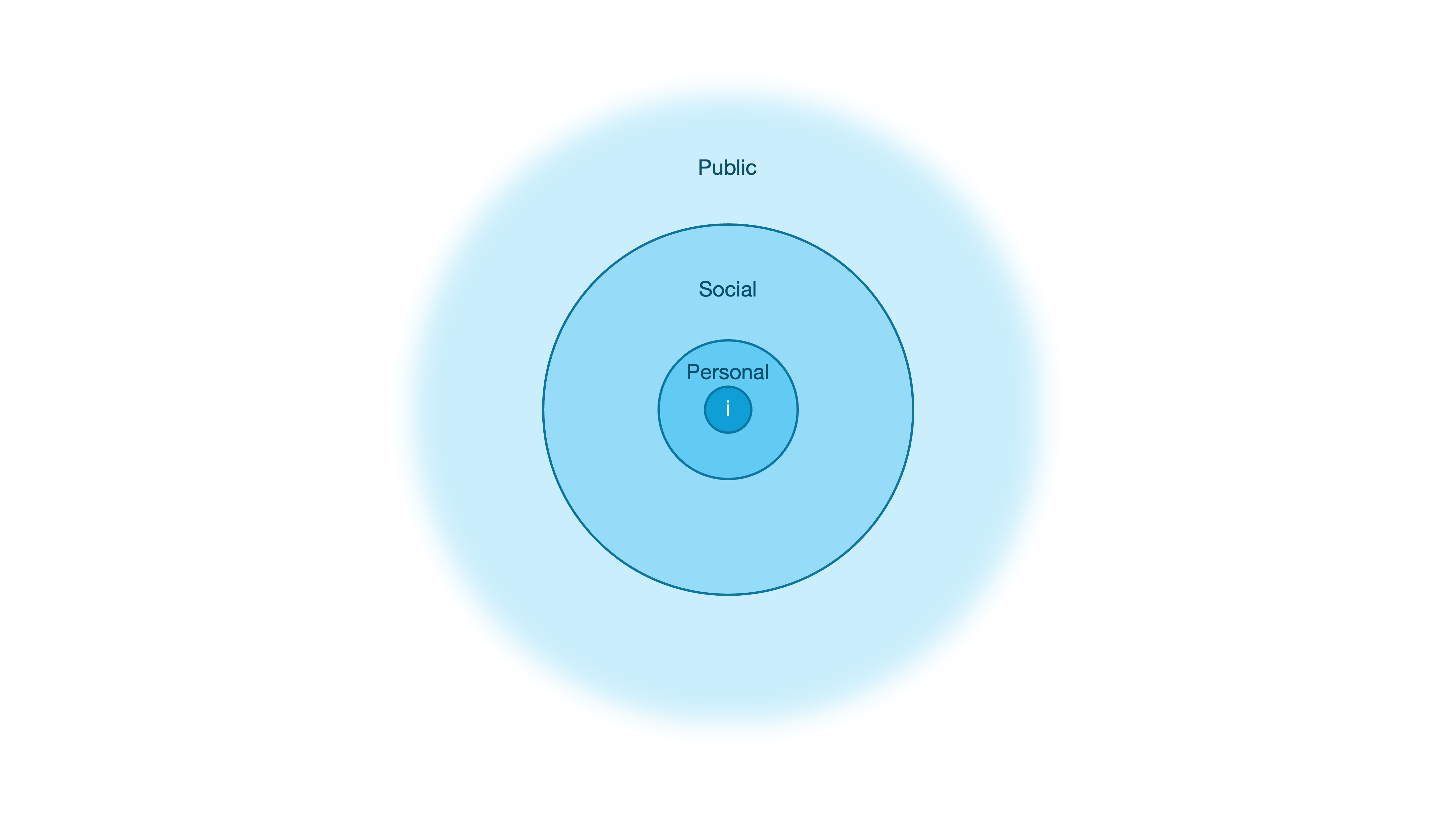
While coordinate systems define the logical structure of space, proxemics introduces the human dimension—how people perceive and react to spatial proximity. Proxemics is the study of personal space and social distance, and in virtual reality, it plays a crucial role in shaping interactions that feel natural, respectful, and emotionally comfortable. Designers must account not only for functional placement but also for the psychological boundaries users instinctively maintain. Respecting these spatial expectations can significantly enhance immersion and reduce discomfort. The zones of personal space in VR include:
- Intimate Space (0–0.5m): Reserved for close personal interactions, such as handoffs, high-trust exchanges, or haptic feedback experiences. Avoid placing avatars, tools, or UI elements in this space unless the user has explicitly initiated the interaction.
- Personal Space (0.5–1.5m): Ideal for one-on-one conversations, small-scale tasks, or interactive UI panels. This is the user’s primary comfort zone—frequently used for interaction and control, so intrusions should be intentional and minimal.
- Social Space (1.5–4m): Best suited for group interactions, multiplayer collaboration, or shared environments. Arrange participants or elements to encourage communication while preserving personal boundaries.
- Public Space (4m+): Appropriate for presentations, lectures, or passive observation. Use this zone for content delivery that doesn’t require direct engagement, such as signage, broadcasts, or performances.
Designing with proxemics in mind ensures that your VR experiences are not only technically accurate—but also socially intuitive. Always test interactions at different distances and in varied user postures (e.g., standing, seated, crouching). Pay attention to how users respond to avatar proximity, reachability, and UI positioning. To reduce discomfort and maintain boundaries, consider subtle visual cues like fading, blurring, or scaling of objects that breach a user’s personal space. In XFactory, for example, invisible boundaries or warning overlays are essential around active machinery like CNC mills or robotic arms—balancing safety with immersion.
Locomotion in VR
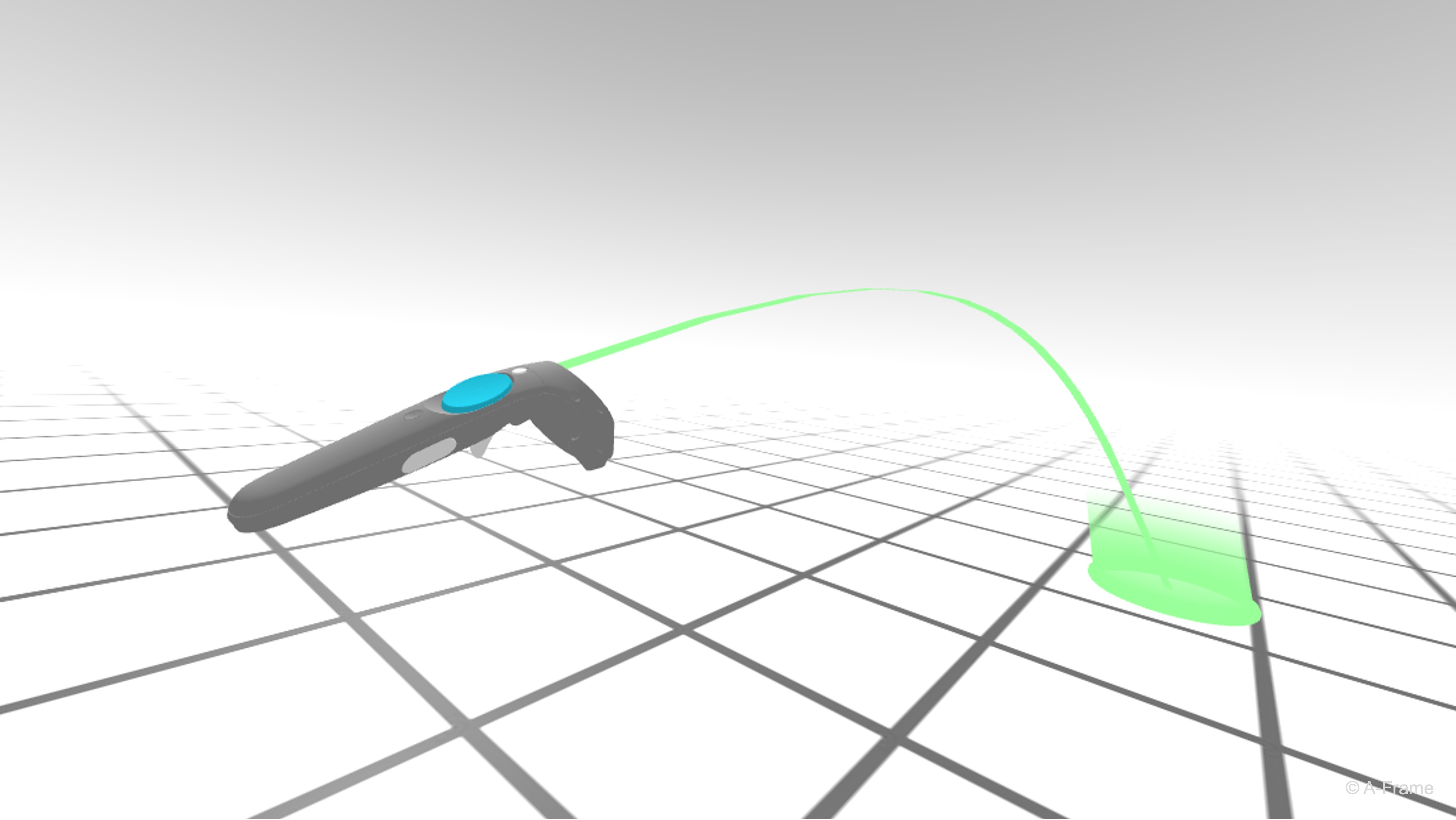
Locomotion is the method by which a user moves through and interacts with a virtual environment. In VR, effective locomotion is critical to creating an immersive, natural, and comfortable experience. Unity’s XR Interaction Toolkit provides a range of locomotion primitives—including teleportation, snap turning, continuous turning, and continuous movement—that can be tailored to suit different applications. For beginner users start with teleportation + snap turn. Add continuous move/turn only when the task requires it, and always provide comfort settings or an alternative locomotion mode. Key considerations in designing VR locomotion include:
- User Comfort and Safety: Design locomotion to minimize motion sickness and disorientation. Use snap turn and teleportation as safer defaults in dense factory scenes; tune move speed, turn amount, debounce time, vignette/tunneling, acceleration, and fade/transition effects when adding continuous locomotion. Some users cannot physically turn easily, while others are sensitive to artificial motion—locomotion options should remain configurable.
- Centralized Input Handling and Interaction Safety: Favor action-based input through
XRI Default Input Actionsrather than device-specific bindings. TheLocomotion Mediatorcoordinates locomotion requests, but snap turn and continuous turn should not both be enabled for the same user control at the same time. - Coordinate Space Management and Transformations: Precisely manage conversions between device, local, and world coordinate spaces. Accurate transformation is essential for maintaining spatial consistency, immersion, and aligning CAD assets, robot cells, controller-relative input, and teleport destinations.
- Modularity, Scalability, and Flexibility in Movement: Build locomotion systems with modularity in mind using XRI Starter Assets and provider components. Teleport anchors can represent safe inspection points, machine stations, control panels, or training task positions, while continuous movement can support close inspection only when safety boundaries and collision geometry are respected.
In XFactory, users can explore the factory floor to observe different stations. Continuous movement lets them walk beside a moving forklift, while teleportation allows them to quickly reposition near a drone landing pad or machinery entrance. Snap turning allows the user to interact with screens or robots placed in a circular formation without physical turning.
XR Origin and Locomotion
The XR Origin component and its root GameObject represent the tracked user in the scene. Locomotion providers move the XR Origin root so the camera and controllers remain spatially coherent. In your XFactoryVR scene, use the XR Origin (XR Rig) you copied from the VR Template SampleScene in D1—not a separate course-provided prefab. Unity may label this object XR Origin (XR Rig) or a similar XR Origin name; identify it by the active Main Camera, left/right controller or interactor child objects, and the locomotion setup beneath it. When locomotion runs—whether teleportation, continuous movement, or turning—providers update that root GameObject so the head (camera) and hands (controllers) stay aligned. The copied VR Template hierarchy typically resembles the structure below:
XR Origin (XR Rig)
├── Camera Offset
│   ├── Main Camera
│   ├── Gaze Interactor
│   ├── Left Controller
│   ├── Left Controller Teleport Stabilized Origin
│   ├── Right Controller
│   ├── Right Controller Teleport Stabilized Origin
│   ├── Left Hand
│   └── Right Hand
└── Locomotion
    ├── Turn
    ├── Move
    ├── Teleportation
    ├── Climb
    ├── Gravity
    └── Jump
XR Origin (XR Rig)
The root GameObject copied from the VR Template that encapsulates the tracked player setup. It is the main locomotion target, meaning that when teleportation or other movement occurs, providers (e.g., Teleportation Provider, Dynamic Move Provider) apply position and rotation changes directly here.
XR Origin: Defines the origin point for XR tracking, ensuring alignment of the player’s position and orientation with the real-world space.Character Controller: Provides collision detection and physics-based constraints for the player (e.g., preventing walking through walls). It defines capsule height, radius, and step offset for grounded movement.Input Action Manager: Handles input bindings by referencing theXRI Default Input Actionsasset, which manages actions like movement, interaction, and teleportation across devices. Input actions must be enabled at runtime through this manager, Project-wide Actions, or the configured Starter Assets prefab setup.XR Input Modality Manager: Manages the player’s current input mode (e.g., controller vs. hand tracking) and ensures the system dynamically switches input handling as needed.
Camera Offset
An intermediary transform that adjusts vertical alignment of the headset relative to the play area. It accounts for standing, seated, or room-scale setups.
Main Camera: Represents the user’s head. Driven by the physical headset, its position and rotation are critical for determining direction and teleportation destinations.Left Controller/Right Controller: Represent the physical hand controllers. These often containXR Ray InteractororXR Direct Interactor, enabling pointing, grabbing, and teleport targeting.Left Controller Teleport Stabilized Origin/Right Controller Teleport Stabilized Origin: Provide stable reference points for initiating teleport actions, helping reduce jitter or inconsistencies during teleport aiming.Left Hand/Right Hand: Represent tracked hand visuals and hand-based interactors when hand tracking is enabled. Depending on the VR Template version, these may include poke interactors, hand rays, or other hand interaction components alongside—or instead of—controller-based input.
Locomotion
A collection of locomotion-related providers and behaviors that extend user movement beyond basic head tracking.
Turn: Enables snap or smooth turning of theXR Origin.Move: Provides directional continuous movement controlled by the thumbstick.Teleportation: Handles teleport-based locomotion using controller input.Climb: Adds climbing mechanics for interactable climbable surfaces.Gravity: Applies gravity to theXR Origin, ensuring grounded movement.Jump: Allows the user to perform jump actions in supported environments.
Locomotion Components
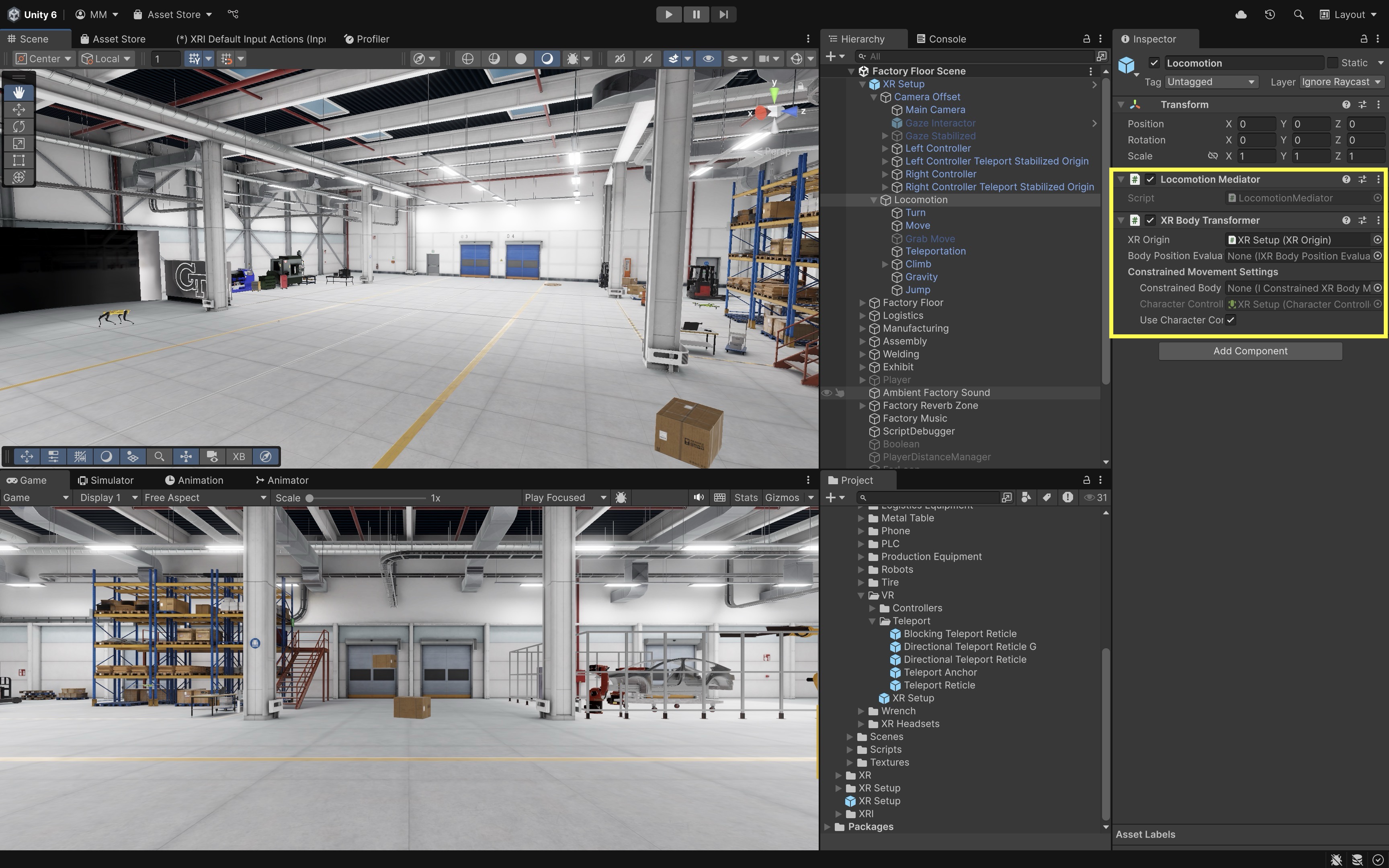
Two key components—the Locomotion Mediator and the XR Body Transformer—work together to coordinate input-driven locomotion and apply it safely to the XR Origin.
- Locomotion Mediator: The
Locomotion Mediatormediates locomotion requests and provides locomotion providers with access to the linkedXR Body Transformer. Multiple locomotion providers can coexist in XRI 3.x, but students should explicitly assign mediator and body transformer references in tutorials to make setup and debugging clearer. Providers can often auto-find the mediator if not assigned, but explicit wiring is more reliable for learning. - XR Body Transformer: The
XR Body Transformerqueues body transformations and applies them to the XR Origin duringUpdate. Once a locomotion provider receives access through the mediator, it delegates movement operations to theXR Body Transformer.Transformation Prioritycontrols queue/order for body transformations rather than acting as a general “only one provider in the whole scene” switch. This component must be present for theLocomotion Mediatorto function correctly.
AI-generated XRI locomotion instructions often mix older
Locomotion System, newerLocomotion Mediator,XR Rignaming, and manual input binding workflows. When locomotion fails, verify package version, Starter Assets, input action references, enabled actions, mediator/body transformer references, interaction layers, colliders, and OpenXR runtime settings before rewriting scripts.
Locomotion Providers
Locomotion providers are modular XRI components that implement specific movement behaviors—teleportation, snap turning, continuous turning, and continuous movement. Each provider requests locomotion through the Locomotion Mediator and applies transformations through the XR Body Transformer. In your copied VR Template setup under XR Origin (XR Rig), inspect or configure these providers in the Locomotion hierarchy. XRI also supports advanced options such as Teleportation Multi-Anchor Volume, but this session focuses on the core providers below.
- Teleportation Provider: Moves the
XR Origininstantly to a point on a Teleportation Area or Teleportation Anchor. - Snap Turn Provider: Rotates the user in fixed angular steps (for example, 45° or 90°) to reduce motion sickness.
- Continuous Turn Provider: Rotates the
XR Originsmoothly over time from thumbstick input. - Continuous Move Provider: Translates the user smoothly through the scene using a configured forward/movement source.
- Dynamic Move Provider: Extends continuous movement with head- or controller-relative direction for forward, backward, and strafe travel.
Before starting this session, confirm that your D1
XFactoryVRscene contains the complete VR Template XR setup copied fromSampleScene—including theXR Origin (XR Rig),Input Action Manager,XR Interaction Manager, locomotion objects, interactors, and enabledXRI Default Input Actions—and that OpenXR and interaction profiles are configured from D1.
Continuous Turn Provider
The Continuous Turn Provider rotates the XR Origin smoothly over time based on user input. While it offers a fluid rotation experience, it is less comfortable than snap turn for many users and must be carefully calibrated—overly rapid or prolonged turning can cause discomfort or motion sickness. Snap turn is usually the beginner/default comfort option; continuous turn is useful for specific applications but should be tuned carefully. A Tunneling Vignette Controller or equivalent comfort vignette can help reduce discomfort during smooth turning, but students should still test comfort in headset. Developers often tie this to the horizontal axis of the right-hand joystick and adjust turn speed to strike a balance between responsiveness and comfort. It is best used in open spaces where users need to orient themselves frequently without relying on teleportation. Follow the instructions below to set it up.
- Add a
Continuous Turn Provider:- Right-click on the
LocomotionGameObject and selectCreate Empty. Name the empty GameObjectTurn. - In the
Inspector, add theContinuous Turn Providercomponent toTurn. - In the
Mediatorfield, assign the existingLocomotion Mediatorcomponent in the scene. This ensures the turning provider cooperates with other movement systems like teleportation or continuous movement. - Ensure the
XR Body Transformeris also attached to the same GameObject as theXR Origin. It is responsible for applying the rotational changes generated by the turn provider.
- Right-click on the
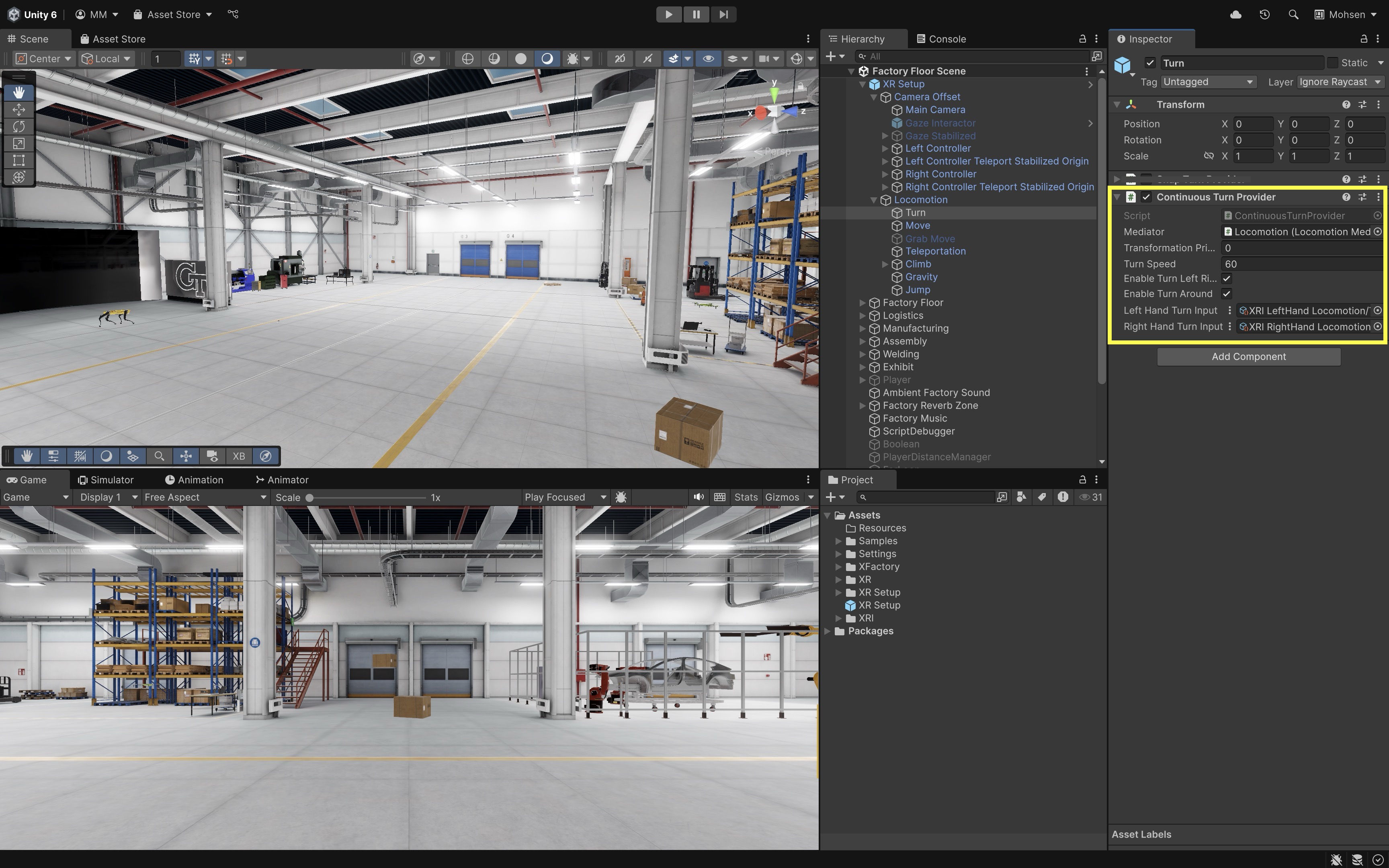
- Configure Turning Parameters:
Transformation Priority: Set this to0. It controls queue/order for body transformations relative to other providers.Turn Speed: Set the speed of rotation in degrees per second (e.g.,60for a smooth turning feel).Enable Turn Left/Right: Check this box to allow the user to rotate left or right using the assigned input action (typically the thumbstick or trackpad). Disabling it will prevent lateral continuous turning.Enable Turn Around: Check this box to enable a 180° turn input, allowing the user to quickly face the opposite direction. This is useful in fast-paced experiences where reorientation is needed.
- Set Up Input Actions:
- The
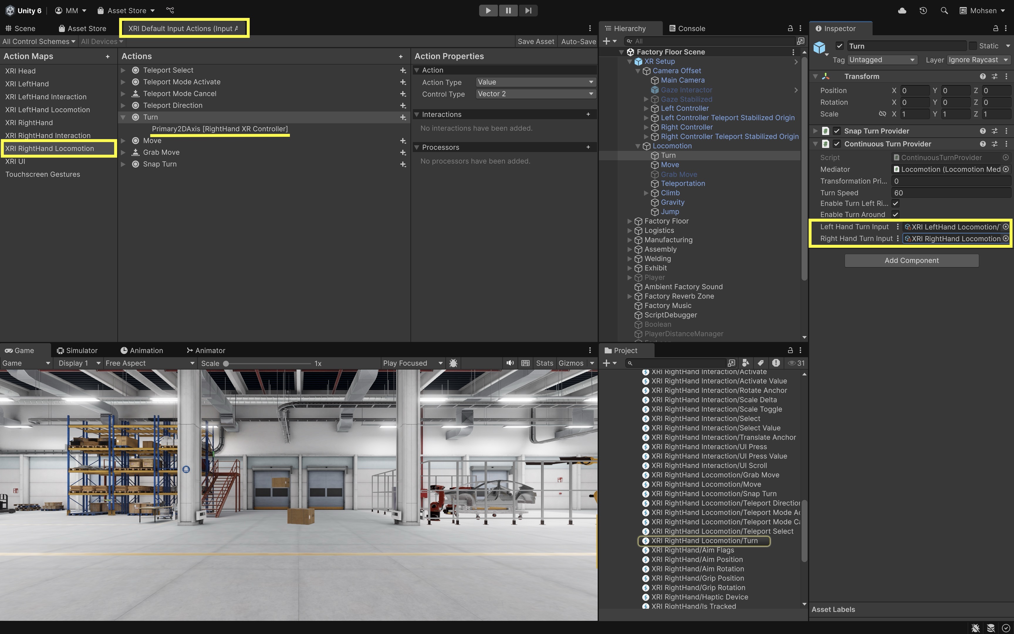
Left Hand Turn InputandRight Hand Turn Inputfields acceptValueactions withVector2control type fromXRI Default Input Actions. Each provider reads the relevant axis from that Vector2 input. - In the
Continuous Turn Provider, click the circle (object picker) icon next to theRight Hand Turn Inputfield. - Choose the matching turn action from
XRI Default Input Actions(for example,XRI RightHand Locomotion/Turn—names may vary slightly by Starter Assets version). - Repeat the above for the
Left Hand Turn Inputfield if you want left-hand turning.
- The
- Run the Scene:
- Enter
Playmode and test with the XR Interaction Simulator, Quest Link / Meta Horizon Link (Windows), or an Android build on Quest as described above.
- Enter
- Observe and Tune:
- In the
Sceneview, watch theXR Originrotate around its vertical axis (Y-axis) and verify it’s pivoting from the base. - Adjust the
Turn Speedin theContinuous Turn Providerfor more comfortable or responsive rotation. - Use
Debug.Log("XR Origin Y-Rotation: " + transform.eulerAngles.y);to confirm that smooth turning functions independently of other locomotion methods like movement or teleportation. If rotation feels misaligned, verify theXR Origin’s structure and ensure input actions are assigned correctly and enabled through theInput Action Manager.
If your setup already includes a
Snap Turn Provider, disable theContinuous Turn Provider(and vice versa). Keep only one active turn provider at a time for the same user control. - In the
Snap Turn Provider
The Snap Turn Provider rotates the XR Origin by a fixed angle—such as 45° or 90°—whenever a valid turn input is detected. Because it avoids smooth, continuous rotation, snap turning reduces visual motion and lowers the risk of motion sickness. It is especially useful in confined or object-dense environments like XFactory, where quick reorientation is needed without displacing the user. For most first-time VR users, snap turn plus teleportation is a safer default than continuous turn plus continuous movement. Snap turn is commonly paired with teleportation for maximum comfort and usability. Here is how it is set up.
- Add a
Snap Turn Provider:- Select your
TurnGameObject. - In the
Inspector, add theSnap Turn Providercomponent. - Assign the existing
Locomotion Mediatorto theMediatorfield to ensure that the snap turn provider integrates smoothly with other locomotion systems. - Confirm that an
XR Body Transformercomponent is attached to the same GameObject as theXR Origin. This component handles the actual rotational transformation requested by the snap turn provider.
If your setup already includes a
Continuous Turn Provider, be sure to disable it. Only one turn provider should be active at a time to avoid conflicts between smooth and snap turning behaviors. - Select your
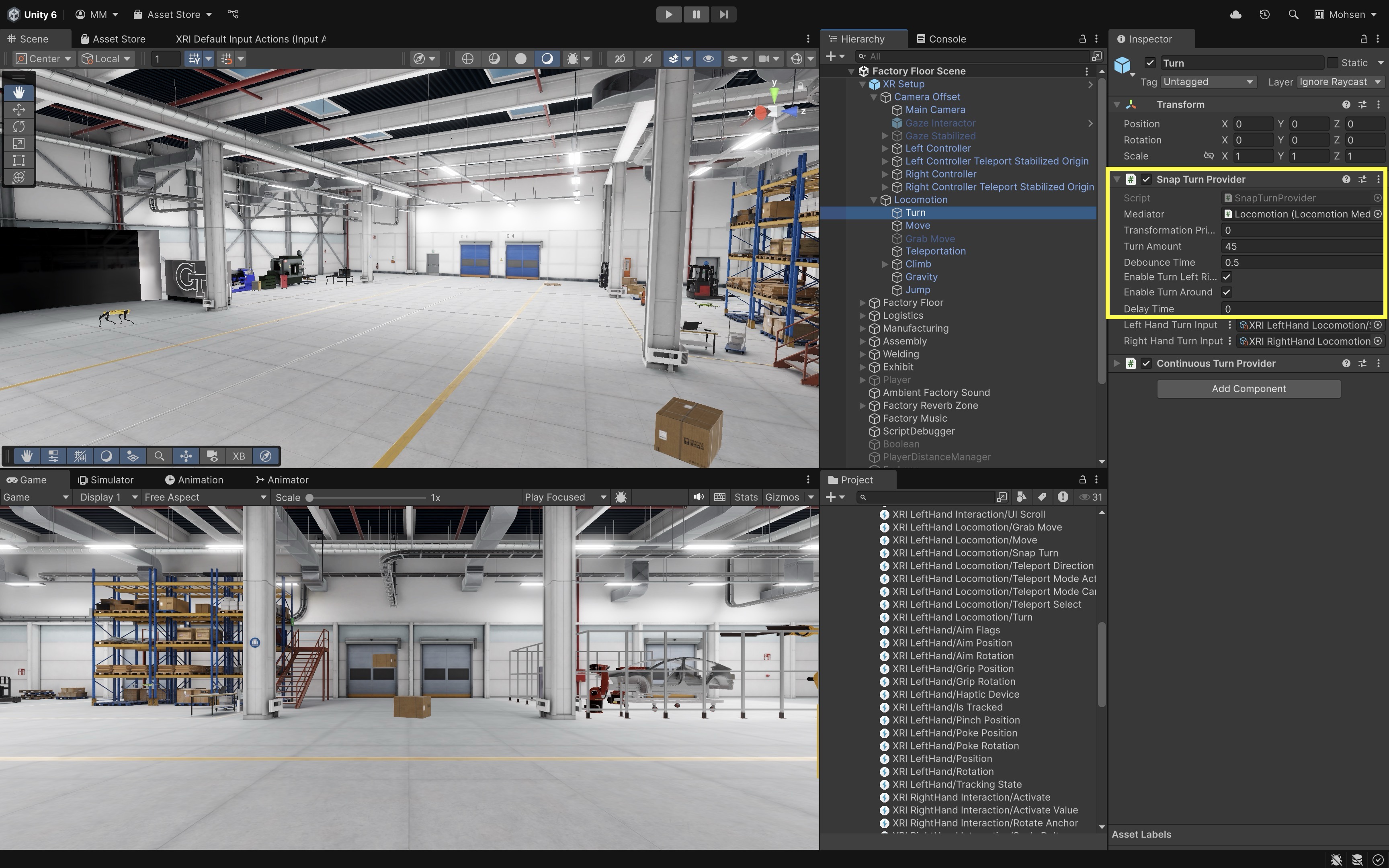
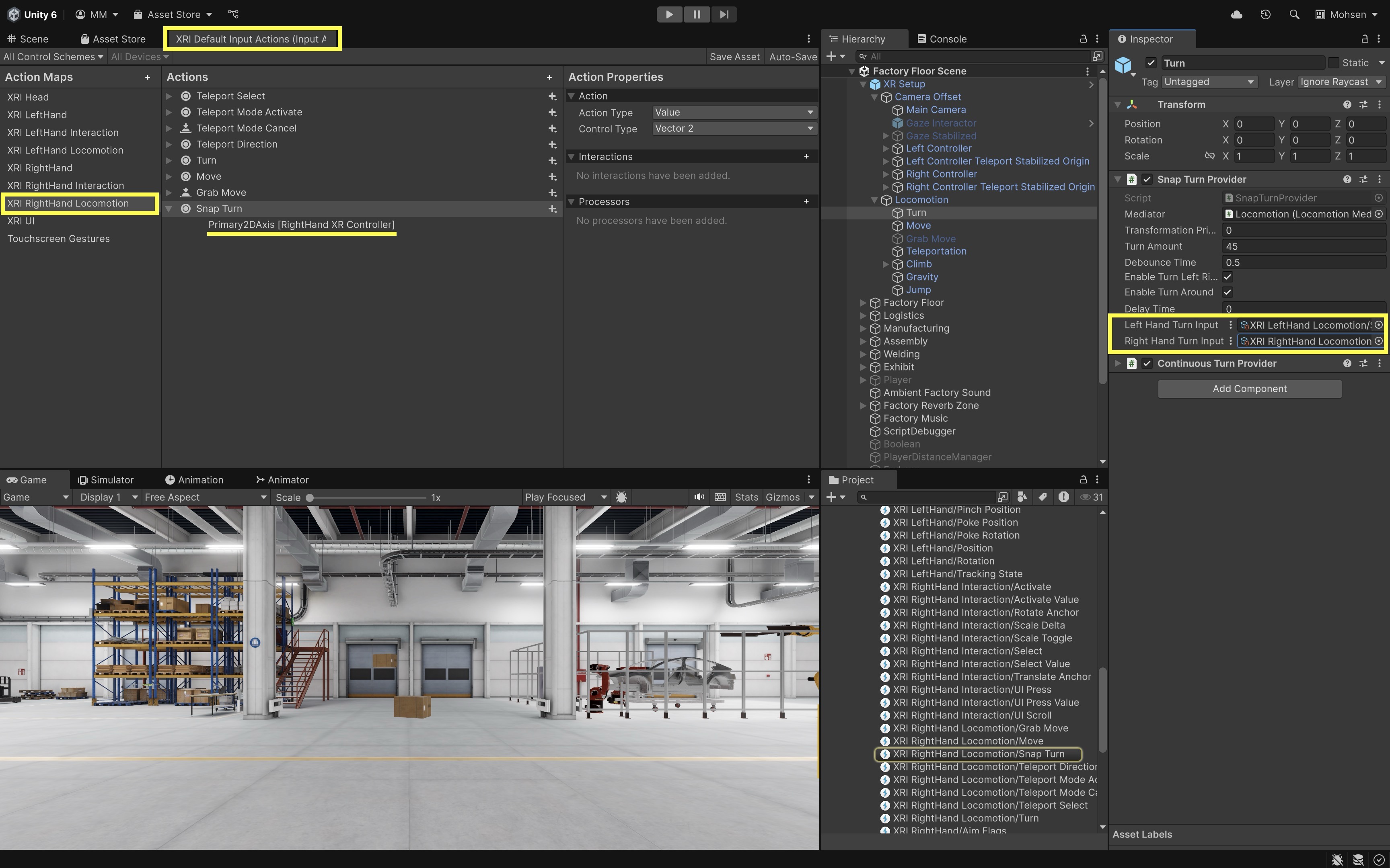
- Configure Snap Turn Parameters:
Transformation Priority: Set this to0unless another provider (like movement) needs to apply first. Lower values apply earlier in the transformation queue.Turn Amount: Choose the angular step for each snap rotation. Typical values are45degrees (more granular) or90degrees (coarser, faster rotation).Debounce Time: Set a delay (e.g.,0.5seconds) between accepted inputs to avoid accidental rapid turning.Delay Time: If visible in the Inspector, use this to delay the first turn—for example, to support a vignette transition.Enable Turn Left Right: Enable it to allow left and right snap turns.Enable Turn Around: Optionally enable this if you want to support a 180° turn action using a separate input. This is useful in tight or back-facing scenarios.
- Assign Input Actions:
- The provider includes
Left Hand Turn InputandRight Hand Turn Inputfields, each expecting aValueaction withVector2control type fromXRI Default Input Actions. The provider uses the relevant axis from that Vector2 input. - Click the circle (object picker) icon next to the
Right Hand Turn Inputfield. - Choose the matching snap-turn action from
XRI Default Input Actions(for example,XRI RightHand Locomotion/Snap Turn). - Leave the
Left Hand Turn Inputempty unless you wish to support turning via the left-hand joystick.
- The provider includes
- Run the Scene:
- Enter
Playmode and test with the XR Interaction Simulator, Quest Link / Meta Horizon Link (Windows), or an Android build on Quest as described above.
- Enter
- Evaluate Snap Turn Behavior:
- Use the joystick to perform snap turns and verify that the
XR Originrotates instantly by the set angle. - Observe whether the rotation happens cleanly around the XR Origin’s Y-axis and does not affect the camera height or controller offsets.
- Adjust the
Turn Amountfor the right balance between speed and control based on your scene’s layout (e.g., tighter turns in small spaces).
- Use the joystick to perform snap turns and verify that the
- Refine Timing and Feedback:
- If the turn feels too rapid or unintentional, increase the
Debounce Timeto filter out noise or over-triggering. - Optionally, add haptic feedback, sound effects, or UI flashes when a turn is performed to improve user awareness.
- Visual cues—such as a directional arc or quick snap effect—can help users stay oriented after turning in environments with similar or repetitive geometry.
- If the turn feels too rapid or unintentional, increase the
Dynamic Move Provider
The Dynamic Move Provider gradually translates the XR Origin in response to joystick input, allowing users to move smoothly through the virtual world. It extends continuous movement by choosing a movement frame of reference based on head or controller direction. This form of locomotion mimics real-world walking and enhances immersion, but it must be tuned carefully to avoid causing discomfort. Movement typically follows the headset’s facing direction and supports both forward and strafing (sideways) motion. It’s ideal for exploration-based applications where natural, fluid movement is critical. Follow the steps below to set it up.
- Attach the
Dynamic Move Provider:- Right-click on the
LocomotionGameObject and selectCreate Empty. Name the empty GameObjectMove. - In the
Inspector, add theDynamic Move Providercomponent. - In the
Mediatorfield, assign the existingLocomotion Mediatorin the scene. This ensures the movement system cooperates with other locomotion providers like turning or teleportation. - Make sure the
XR Body Transformeris attached to the same GameObject as theXR Origin. It applies the translation updates triggered by the move provider.
- Right-click on the
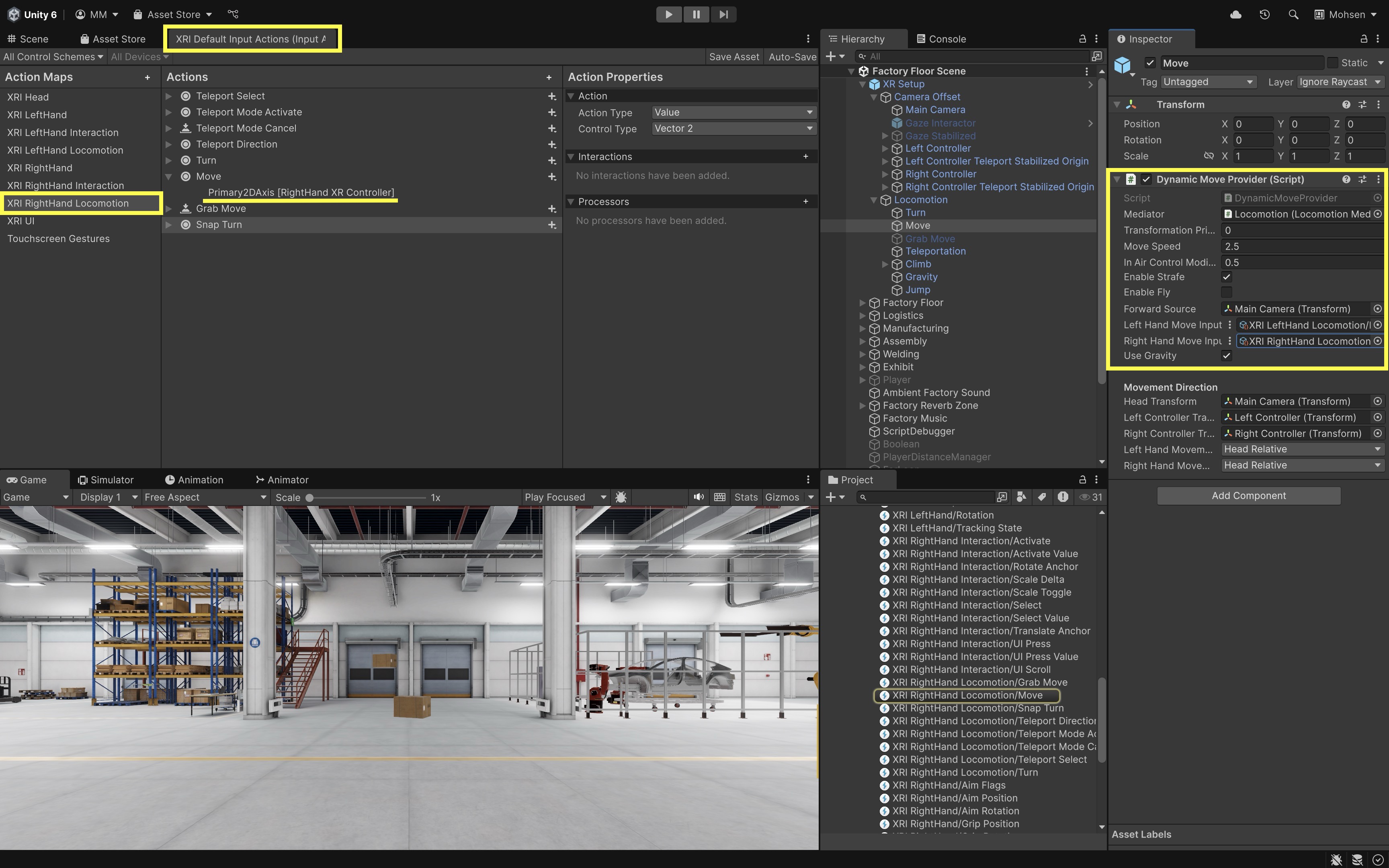
- Configure Movement Parameters:
Transformation Priority: Set this value to define when this movement is applied relative to other providers (e.g., after turning).Move Speed: Set the speed of movement in units per second (e.g.,2.5for walking pace).Enable Strafe: Enable this to allow lateral (sideways) movement from joystick input.- Click the circle (object picker) icon next to the
Left Hand Move Inputfield. - Choose the matching move action from
XRI Default Input Actions(for example,XRI LeftHand Locomotion/Move). Move input usesValueactions withVector2control type (horizontal = strafe, vertical = forward/backward). - Repeat the input setup steps for the
Right Hand Move Inputfield if needed.
- Set Movement Direction:
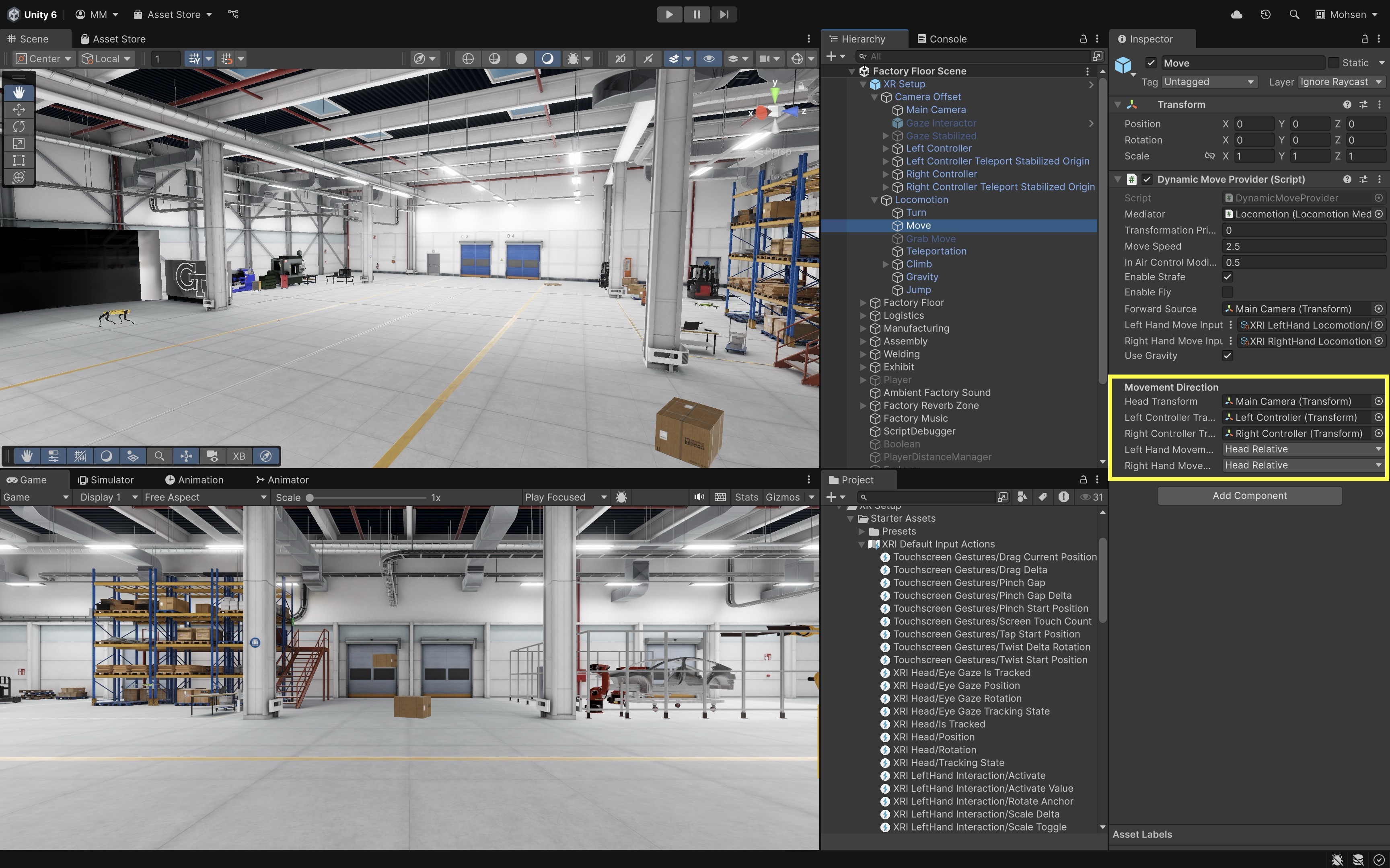
- For
Dynamic Move Provider, assign the head and controller transforms used to determine movement direction. When using a plainContinuous Move Provider, theForward Sourcecontrols which transform defines forward movement. Head Transform: Assign theMain Camerato align movement direction with the user’s gaze.Left Controller Transform: Assign theLeft Controllerto allow controller-relative input when needed.Right Controller Transform: Assign theRight Controllerfor the same purpose on the right hand.Left/Right Hand Movement Direction: Set this toHead Relativeas the default beginner recommendation so that joystick inputs move the player relative to the user’s current viewing direction.
- For
- Run the Scene:
- Enter
Playmode and test with the XR Interaction Simulator, Quest Link / Meta Horizon Link (Windows), or an Android build on Quest as described above.
- Enter
- Observe and Tune:
- In the
Sceneview, move using the left-hand joystick and observe theXR Origintranslating in space. - Confirm that forward movement matches the headset’s orientation and that the
XR Originmoves at a comfortable speed. - Tweak
Move SpeedandStrafesettings for responsiveness and comfort. - Use
Debug.Log("XR Origin Position: " + transform.position);to confirm that movement is applied in world space and correctly translates joystick input to the expected direction and magnitude. If movement appears off-angle, double-check thatHead Transformand the per-hand movement direction settings are assigned correctly.
Continuous movement is more likely than teleportation to cause discomfort. Start with slow speeds, avoid sudden acceleration, consider vignette comfort options, and provide teleportation as a fallback. If users should not pass through machines, walls, or safety boundaries, configure a
Character Controlleror constrained movement setup with colliders on the environment. Do not assume theXR Originautomatically collides with factory geometry. Avoid Rigidbody-based movement for the XR Origin. - In the
Teleportation Provider
The Teleportation Provider receives teleport requests from teleportation interactables and moves the XR Origin to a chosen position in the virtual environment. This method avoids the sensory conflict caused by continuous movement, making it highly effective at minimizing motion sickness. It works with Teleportation Area and Teleportation Anchor interactables (and optionally advanced Teleportation Multi-Anchor Volume setups), and is typically triggered via an XR Ray Interactor on the controller. A Teleportation Area allows users to choose a point on a valid surface; a Teleportation Anchor sends users to a predefined position and optionally orientation. Teleportation is ideal for large environments, precision positioning, or setups where natural walking isn’t practical. To setup teleportation, follow the steps below.
- Add a
Teleportation Provider:- Right-click on the
LocomotionGameObject and selectCreate Empty. Name the empty GameObjectTeleportation. - In the
Inspector, add theTeleportation Providercomponent. - In the
Mediatorfield, assign theLocomotion Mediatorfrom your scene. This ensures teleportation integrates cleanly with other movement types. - Verify that the same GameObject also includes an
XR Body Transformer. This component applies the actual transformation—teleporting the user from one location to another.
- Right-click on the
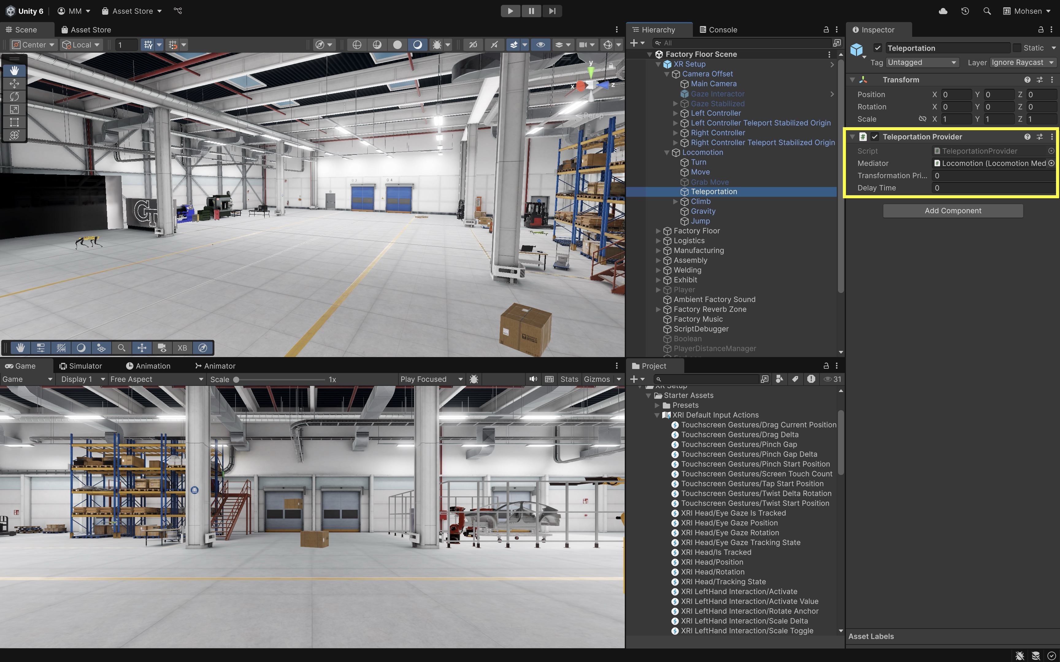
- Configure Teleportation Settings:
Transformation Priority: Set this to0to apply this movement before other providers.Delay Time: Optionally delay teleport execution (e.g., for fade-out effects).
- Assign Controller Input:
- Select the controller you want to use for teleportation (e.g.,
Right Controller). - Ensure the GameObject or one of its children has an
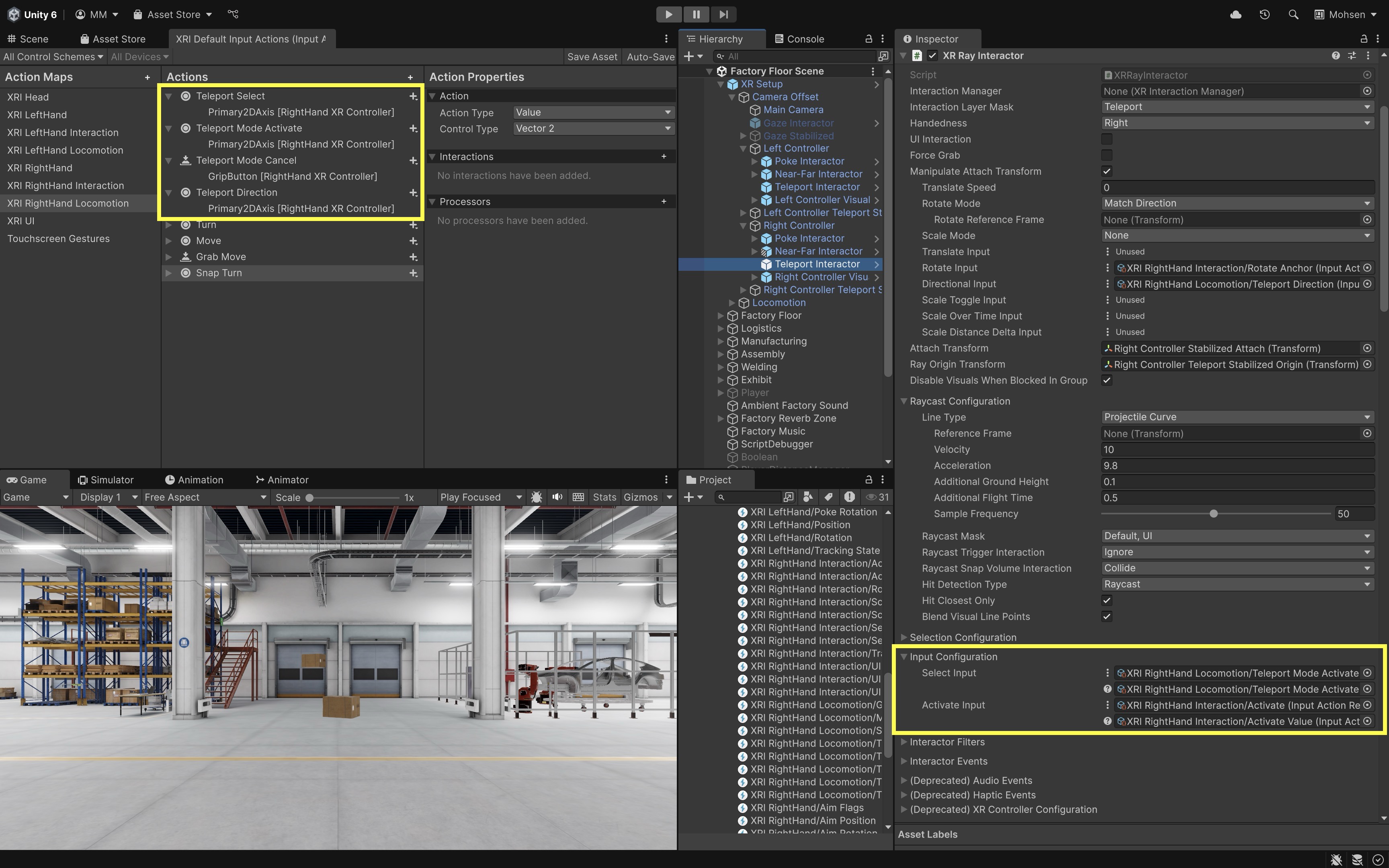
XR Ray Interactorcomponent (e.g., in our case,Teleport InteractorGameObject). - Ensure the
Interaction Layer Maskis set toTeleportso teleport targets are detected during setup and testing. - Starter Assets teleport interactors are usually already wired to
XRI Default Input Actions. Verify the relevantSelect InputandActivate Inputreferences on theXR Ray Interactoronly if teleport mode does not activate—for example, confirm teleport-mode activate and select/activate actions from the default action asset.
- Select the controller you want to use for teleportation (e.g.,
- Set Up
Teleportation Area:- Go to
GameObject > XR > Teleportation Areato create a surface users can teleport to. - Resize and position the area to match your walkable regions (e.g., floors, platforms).
- In the
Teleportation Areacomponent, set theInteraction Managerfield if it is not already populated. Use the sameXR Interaction Managerused elsewhere in your scene. You can leave this field empty as well—it will be populated in runtime. Interaction Layer Mask: Defines which Interactors (e.g., ray, hand) can target this area based on matching interaction layers.Colliders: The physical colliders that mark where teleporting is valid; must exist for raycasts/hits.Distance Calculation Mode: Controls how “closest point” is measured for interaction (e.g., from interactor to surface hit).Custom Reticle: Lets you assign a specific reticle prefab (visual marker) instead of using the default.Select Mode: Determines how selection works (e.g.,Single: one interactor at a time,Multiple: allow many).Focus Mode: Defines how focus is tracked (e.g., whether multiple interactors can “focus”/hover at once).Match Orientation: Aligns the player’s forward direction to the surface normal or target orientation when teleporting.Teleport Trigger: Specifies the input event that actually executes the teleport (e.g., on select enter, on select release).Materials: You can assign a custom material (e.g., transparent or semi-transparent) to theMesh Rendererof theTeleportation Areato better match your scene’s visual style or to make teleport targets less visually intrusive.
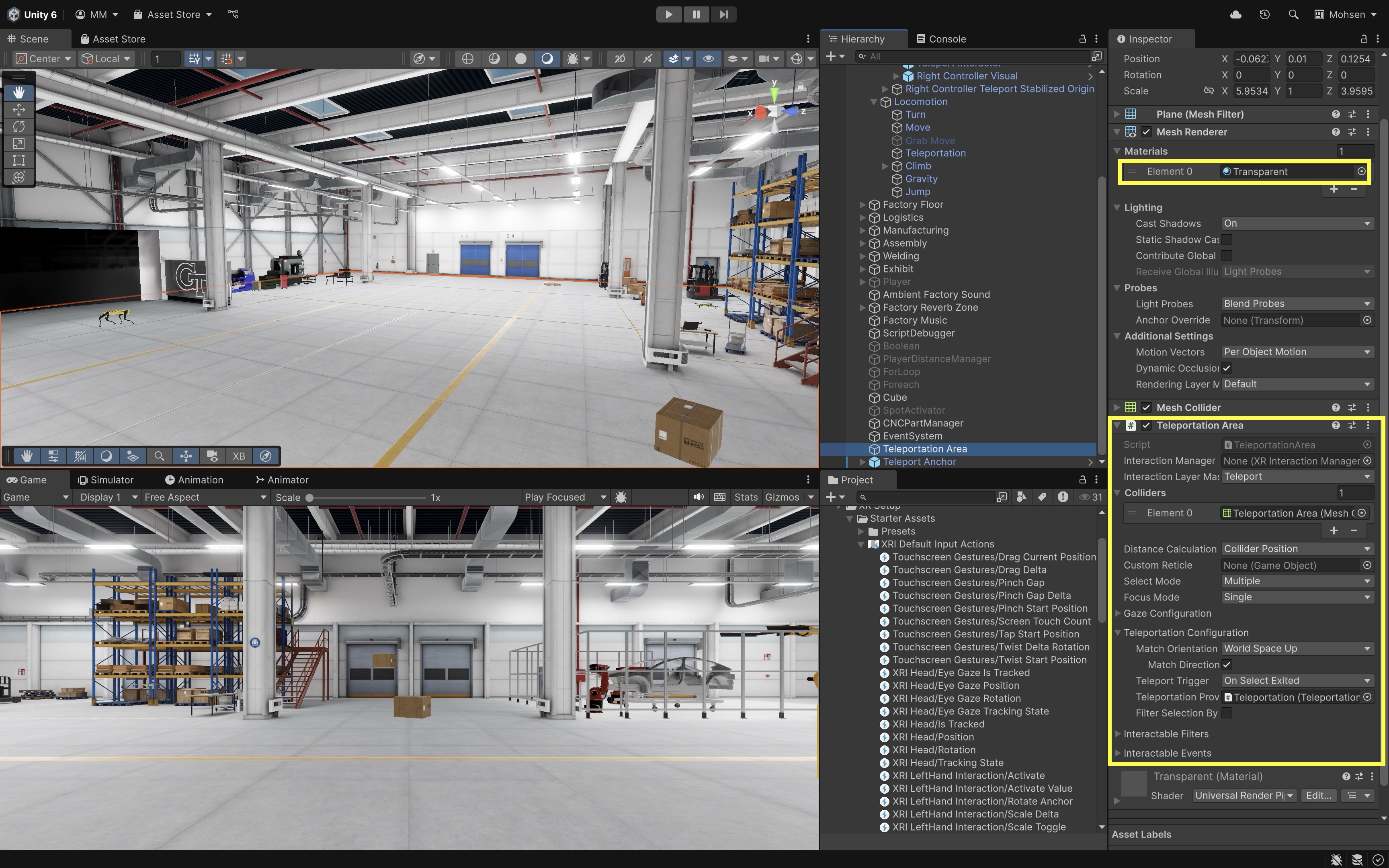
Raise the Teleportation Area slightly above the floor on the positive Position Y axis (for example, 0.01–0.05 m) so its collider sits just above the floor geometry. This helps the teleport ray hit the area reliably instead of missing or conflicting with the floor mesh.
- Go to
- Set Up
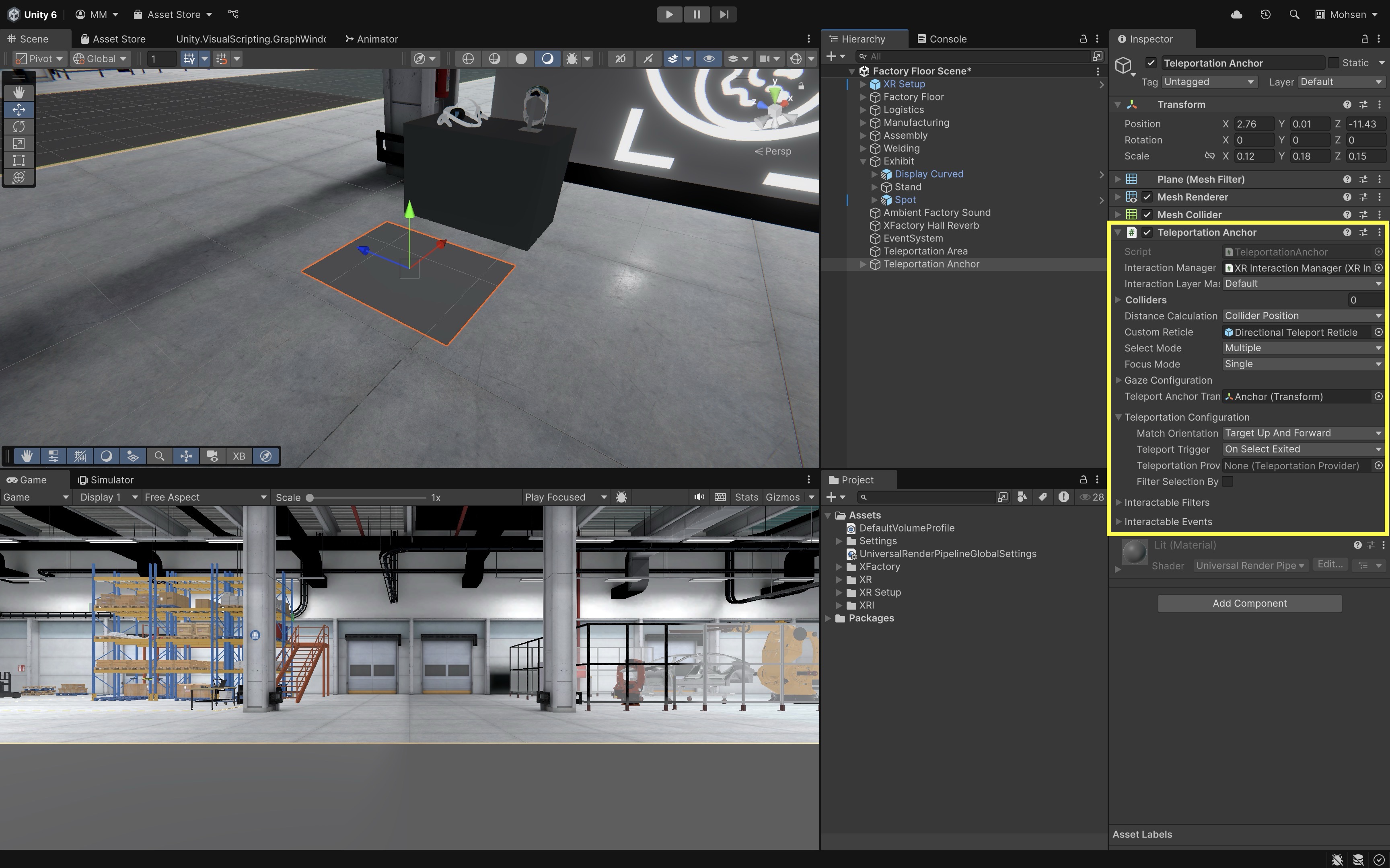
Teleportation Anchor(Optional):- Add a fixed landing spot with a defined orientation via
GameObject > XR > Teleportation Anchor. - Position and rotate the
Teleportation Anchorto control where and how the user will face after teleporting. - In the
Teleportation Anchorcomponent, assign theInteraction Managerfield using the sameXR Interaction Managercopied from the VR Template setup (for example, from the scene root or under yourXR Origin (XR Rig)). Click the circle icon to select it from the scene. - Set the
Match Orientationdropdown based on how you want the user to be aligned after teleporting.Nonekeeps the user’s current orientation.Target Upaligns only the vertical direction (Y-axis).Target Up And Forwardaligns both vertical and forward directions to match the anchor’s transform.
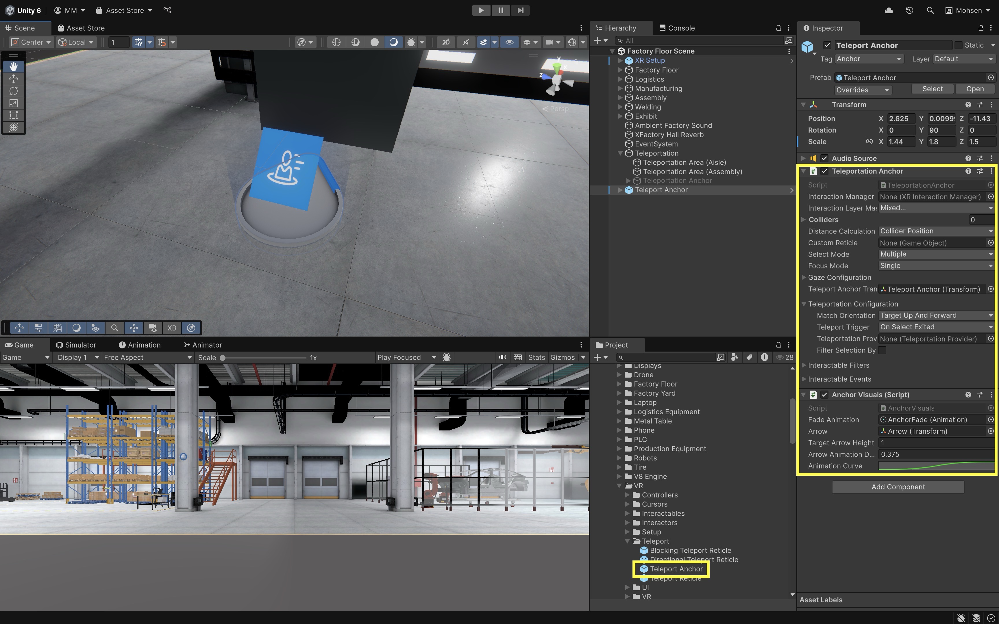
- Optionally, you can replace the anchor with the
Teleport Anchorprefab (provided by Unity) underAssets > XFactory > Prefabs > VR > Teleportto better visualize the position and direction of the teleportation anchor.
- Add a fixed landing spot with a defined orientation via
- Run the Scene and Test Teleportation:
- Enter
Playmode and test with the XR Interaction Simulator, Quest Link / Meta Horizon Link (Windows), or an Android build on Quest as described above. - Aim the controller at a
Teleportation AreaorAnchorusing the ray. - Press the assigned teleportation input (e.g., joystick forward, trigger hold).
- Upon release or confirmation, the
XR Originshould instantly move to the target location.
- Enter
- Fine-Tune Interactions:
- Adjust teleport behavior for instant versus press-and-hold activation.
- Address interaction conflicts, such as grabbing and UI control—use separate layers and input actions to avoid overlap.
- Test in a variety of lighting and environment conditions to ensure visual feedback remains visible and intuitive.
- Make the teleportation area’s material transparent to make it less visually intrusive.
In XFactory, use teleportation areas and anchors to guide users to safe inspection positions rather than letting them land inside machines, conveyors, robots, or blocked maintenance zones. Teleport anchors should represent safe inspection points, machine stations, control panels, or training task positions.
Locomotion Testing Checklist
Before moving on to optimization, verify the following in Play Mode and on device:
- Head tracking works.
- Controller tracking works.
- Input actions are enabled through the
Input Action Manageror Starter Assets setup. - Snap turn or continuous turn works, but not both on the same control at once.
- Continuous move uses the intended forward source (
Head Relativeby default). - Teleport ray hits only valid teleport layers.
- Teleport anchors face the intended direction.
XR Origindoes not clip through floors, walls, or machines if collisions are required.- Quest Link / Meta Horizon Link preview works where available.
- Android build-to-device works on Quest.
- Comfort and scale are verified in headset.
Optimize the Project for VR
Before moving on to other VR topics in the course, pause here to review a short production checklist. The practices below apply to VR projects in general, not only to navigation; they help keep locomotion, interaction, and rendering comfortable on standalone headsets such as Meta Quest 3. 90 FPS is a common comfort target on many headsets, but actual budgets depend on Quest refresh rate, render scale, URP settings, foveated rendering support, lighting, shader complexity, post-processing, physics, and scene content. Poorly optimized VR apps can lead to nausea, discomfort, and system overheating, especially on standalone devices.
Measure Your Performance
- Set a Target Frame Rate: Many VR headsets target 90 FPS or higher for comfort, but refresh-rate settings and device capabilities vary. Refer to your headset specifications (e.g., Meta Quest 3) and document a realistic target for your scene and course hardware.
-
Monitor Frame Rate Using Stats or Script: Click the
Statsbutton in the top-right corner of theGameview to view real-time information such as FPS, draw calls, and triangle count. This is useful for early checks in the Editor. You can also display FPS in the scene using a simple script with1.0f / Time.deltaTime, shown in aTextorTMP_TextUI element for live monitoring.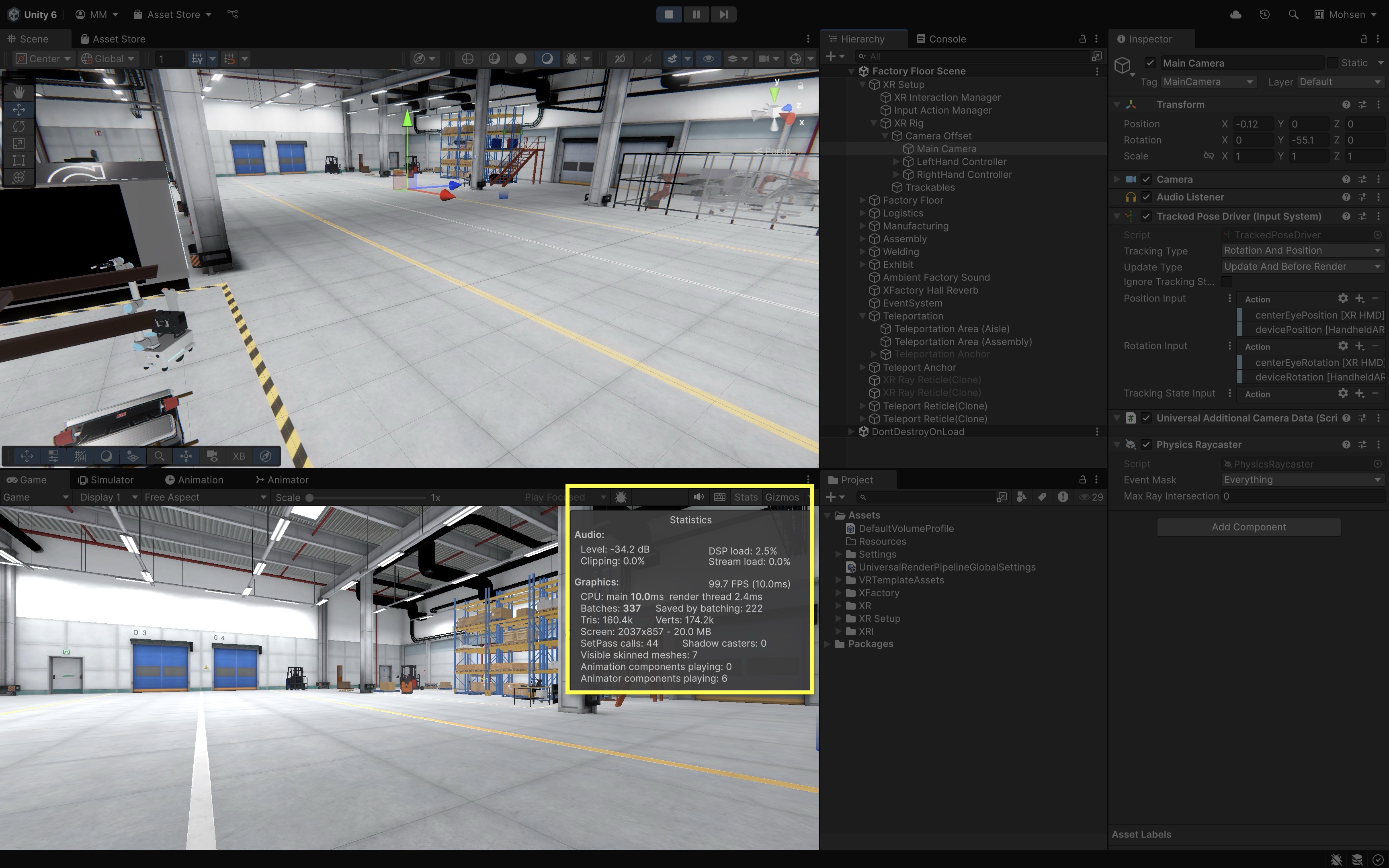
-
Delve Deeper Into Performance Using Profiler: For a deeper look into CPU, GPU, memory, rendering, and script performance, open the Unity Profiler via
Window > Analysis > Profiler. It provides real-time charts and timelines, helping you pinpoint bottlenecks while your application is running.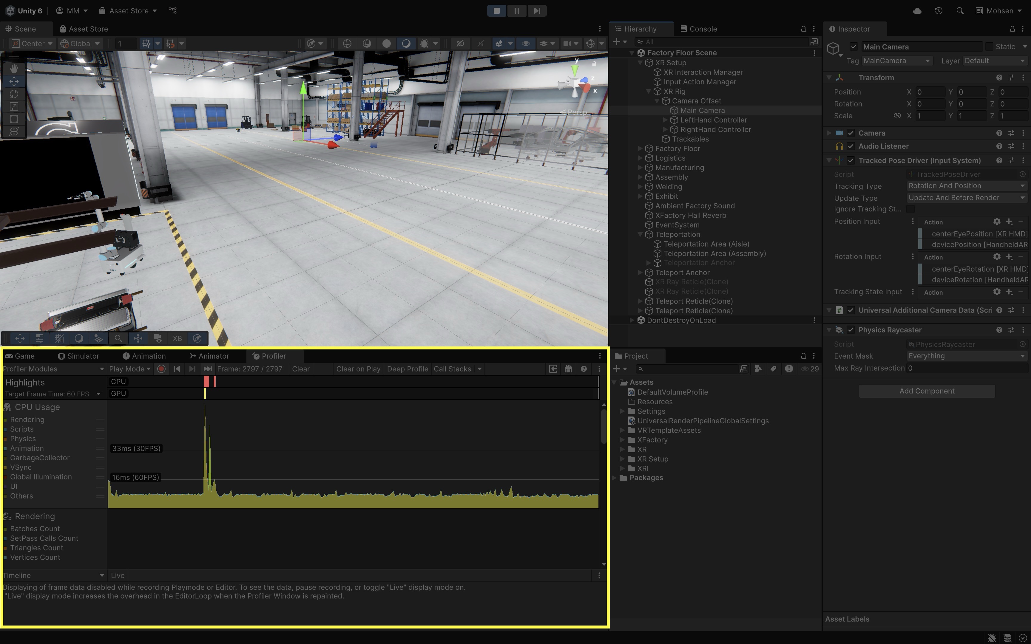
- Test on Device: Editor Stats are useful for early checks, but final performance decisions must be based on device testing with Unity Profiler, Android/Quest profiling tools, and in-headset observation. Build and run on your actual VR hardware. Long sessions can reveal thermal throttling that short Editor tests will not show.
- Monitor Physics Cost: For locomotion and interaction-heavy scenes, monitor active rigidbodies, collision meshes, trigger volumes, and physics update cost.
Minimize Draw Calls
- Check Draw Calls in Stats: Open the
Game View > Statswindow. The “Batches” value shows your draw call count. On standalone Quest testing, ~175 draw calls is a rough starting budget—not a universal rule. In the figure above, for example, the number of batches is over 300, which may be too high for standalone VR depending on scene content and render settings. High draw call counts increase CPU overhead and reduce frame rates, especially on mobile or standalone headsets. -
Use Static Batching: Go to
Edit > Project Settings > Player > Other Settings. EnableStatic Batching. This feature lets Unity group static objects, reducing CPU work needed to send rendering instructions.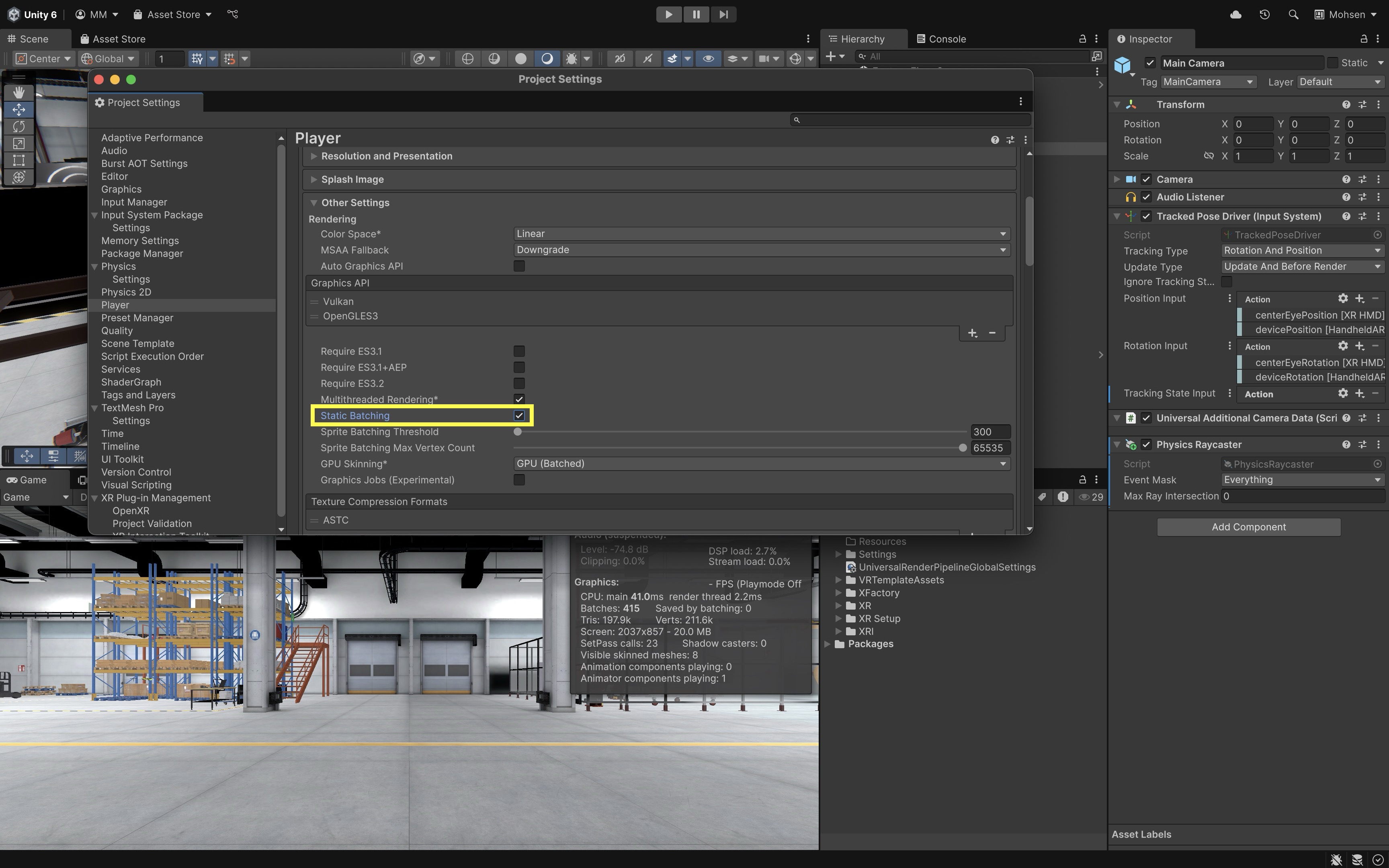
- Mark Static Objects: In the
Hierarchy, select non-moving objects. In theInspector, enable theStaticcheckbox to let Unity batch them. Marking objects as static informs the engine that these do not change, allowing more aggressive performance optimizations like lightmapping and occlusion culling. Only mark objects Static if they do not move, animate, or participate in dynamic interaction. In XFactory, static walls, floors, and large background machinery can be static; moving robots, forklifts, grabbable tools, doors, conveyors, and animated machine parts should not be blindly marked static.
Reduce Polygon Count
- Analyze Triangle Count: In the
Statsview, checkTris(triangle count). UseScene View > Wireframemode to inspect object complexity. On standalone Quest testing, ~500k triangles can serve as a rough starting budget, but acceptable limits depend on materials, lighting, and target hardware—not a fixed rule. Lower triangle counts reduce GPU load, making rendering faster and more efficient, particularly for scenes with many objects. - Inspect Meshes: Select objects and check their
Mesh Filterin theInspector. View the mesh in theProjectwindow to see triangle details. Understanding your models’ complexity helps you spot and replace unnecessary high-poly meshes early in the pipeline. -
Simplify High-Poly Assets: Use modeling tools like Blender or optimization tools like Simplygon to reduce polycounts. Use
LOD Groupcomponents (GameObject > LOD Group) for objects that can have lower detail at distance. This helps maintain high visual quality up close while reducing rendering costs when objects are farther from the camera.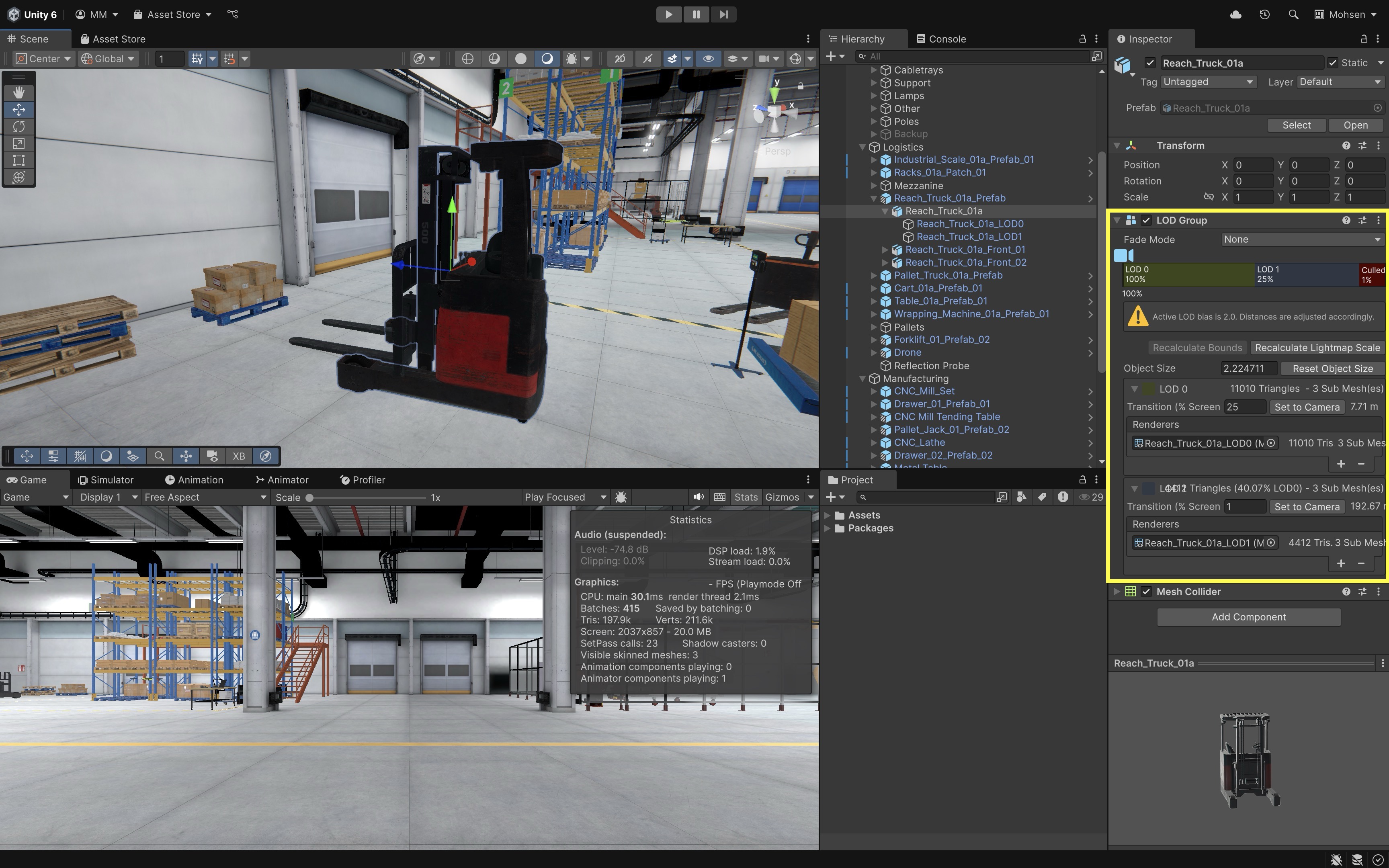
Optimize Textures
- Adjust Import Settings: Select textures in the
Projectview. In theInspector, adjustMax Size,Format, andCompression. Smaller and compressed textures load faster, use less memory, and reduce the bandwidth needed for GPU rendering. - Enable Mip Maps: In the texture import settings, check
Generate Mip Mapsto reduce overdraw at distance. Mip maps improve performance and visual quality by lowering texture resolution for far-away objects, reducing aliasing. -
Use Anisotropic Filtering: Set
Aniso Levelto2–8for floor or angled surfaces to improve sharpness at oblique views. This reduces blurring of textures viewed from shallow angles, such as factory floors or walls, enhancing realism.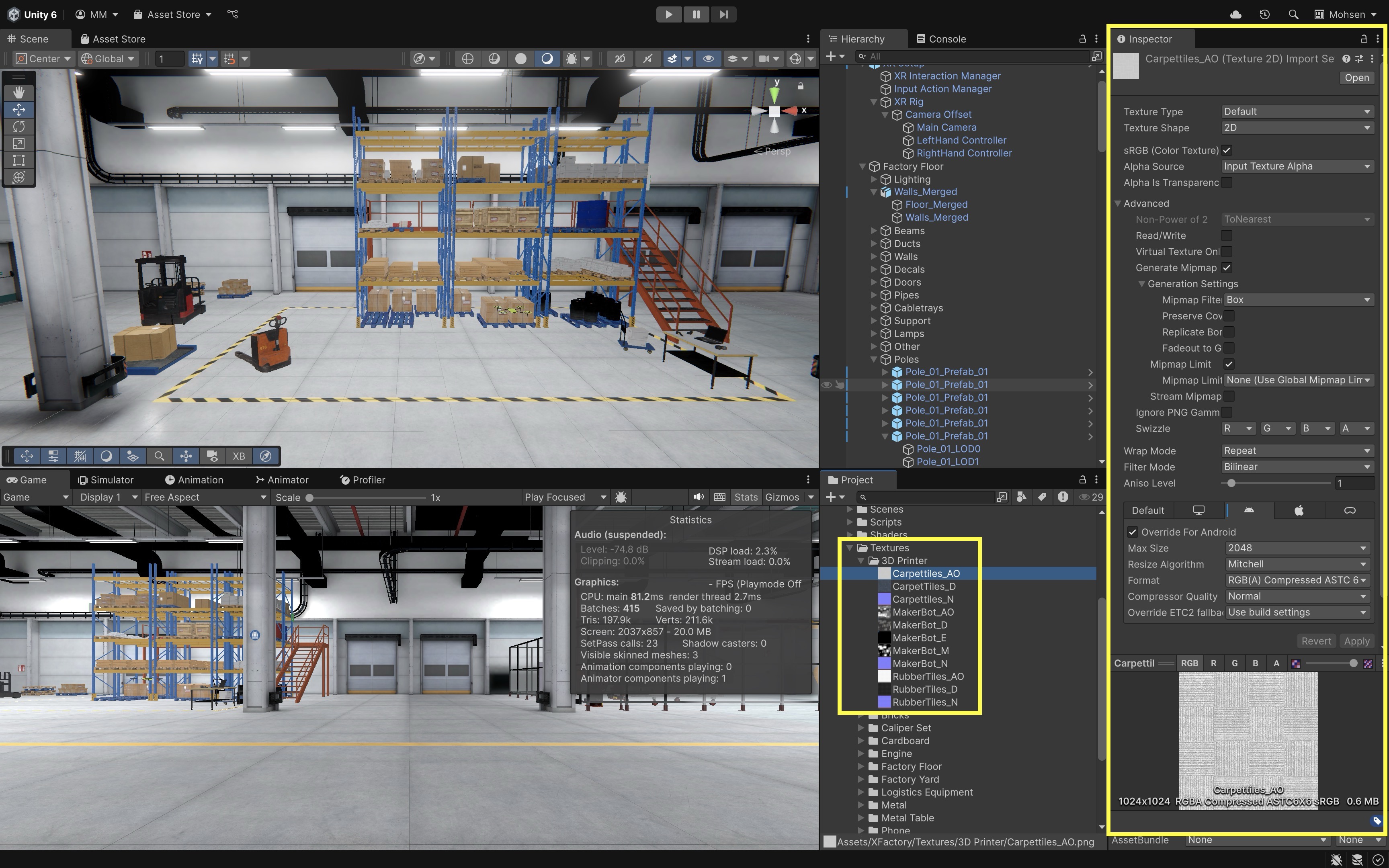
Optimize Particles and Effects
- Simplify Particle Systems: Use
Universal Render Pipeline/Particles/Unlitshaders for particles. Minimize particle count and lifetime. Complex particle systems are expensive and can tank performance quickly in VR; using unlit shaders avoids lighting overhead. - Limit Post-Processing Effects: Add a
Volumeto the Main Camera. Create and assign aVolume Profile. Use only lightweight effects likeColor AdjustmentsorBloom, and avoidMotion Blur,Chromatic Aberration, andLens Distortion. Post-processing can dramatically impact performance and user comfort. Some effects are disorienting or nauseating in VR.
Apply Efficient Anti-Aliasing
-
Set MSAA in URP Asset: Locate your
UniversalRenderPipelineAsset(e.g.,URP-HighQuality). In theInspectorunderQuality, setMSAAto4xwhere supported. Multi-sample anti-aliasing is the preferred VR anti-aliasing path in URP and smooths jagged edges with a moderate performance cost, especially important for headset displays.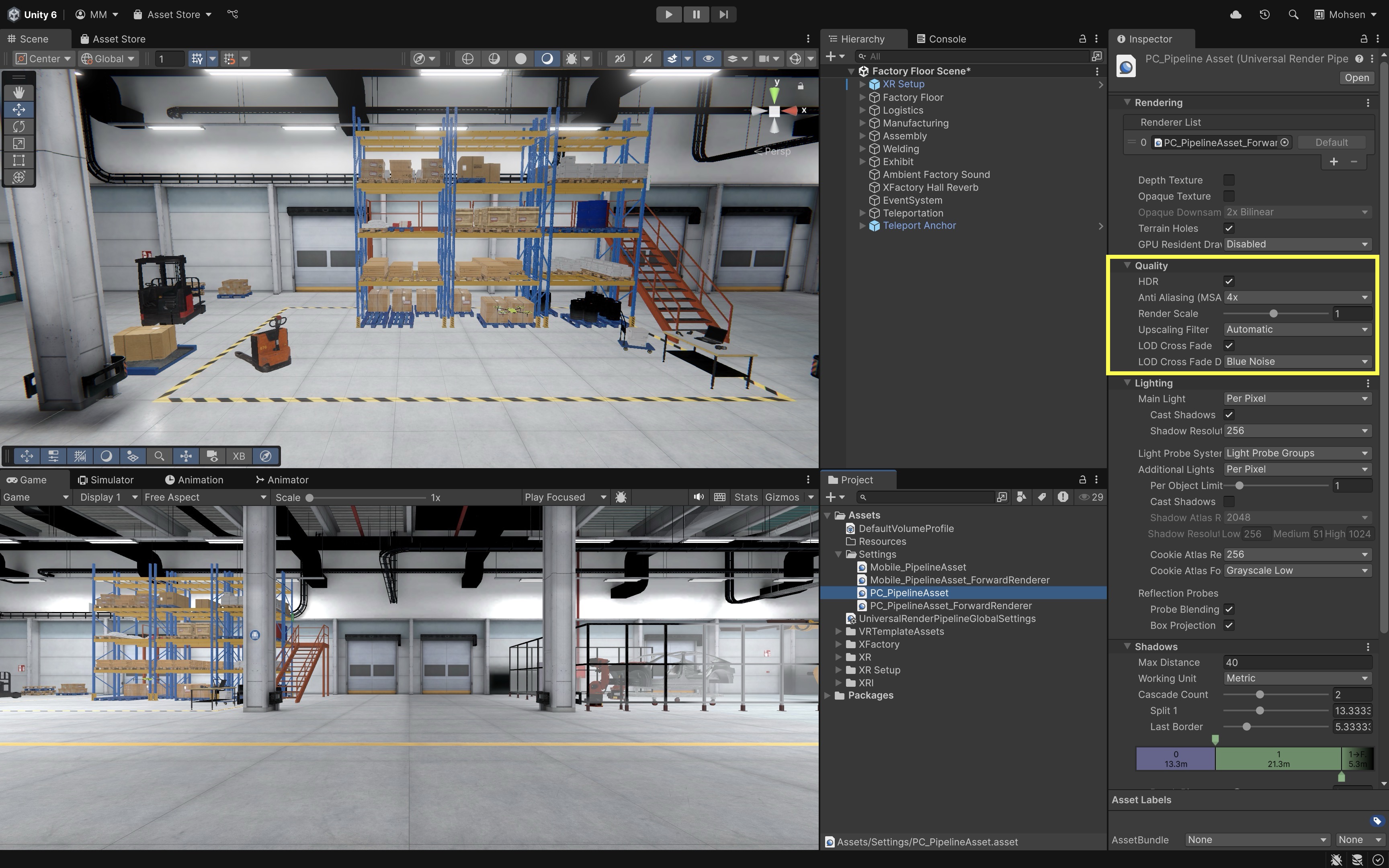
-
Consider FXAA or SMAA as Alternatives: Depending on your pipeline and project settings,
FXAAorSMAAcan be lightweight screen-space alternatives. Do not assume FXAA/SMAA should always be combined with MSAA—choose based on visual quality needs and device performance.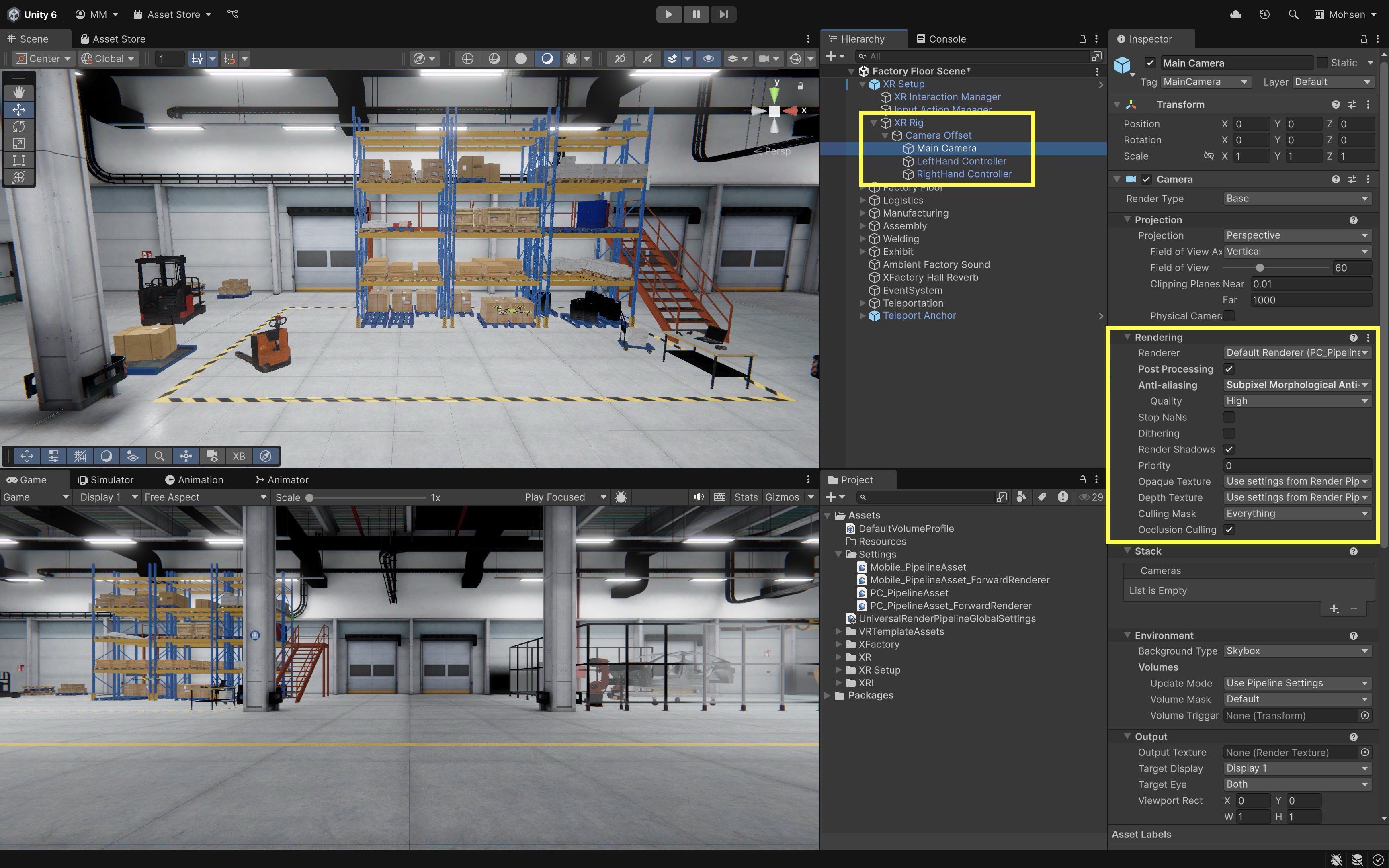
-
Adjust High-Detail Materials: For detailed objects like machines or robots, use baked
Reflection Probesand simpler shaders. Real-time reflections and complex PBR shaders are GPU-intensive and should be avoided or simulated in VR contexts. Avoid motion blur, heavy lens distortion, chromatic aberration, and excessive post-processing in VR.
Additional Tips
-
Occlusion Culling: Open
Window > Rendering > Occlusion Culling. Bake occlusion data to prevent rendering of objects blocked from view. This improves performance by skipping rendering for hidden geometry, especially useful in indoor scenes like XFactory.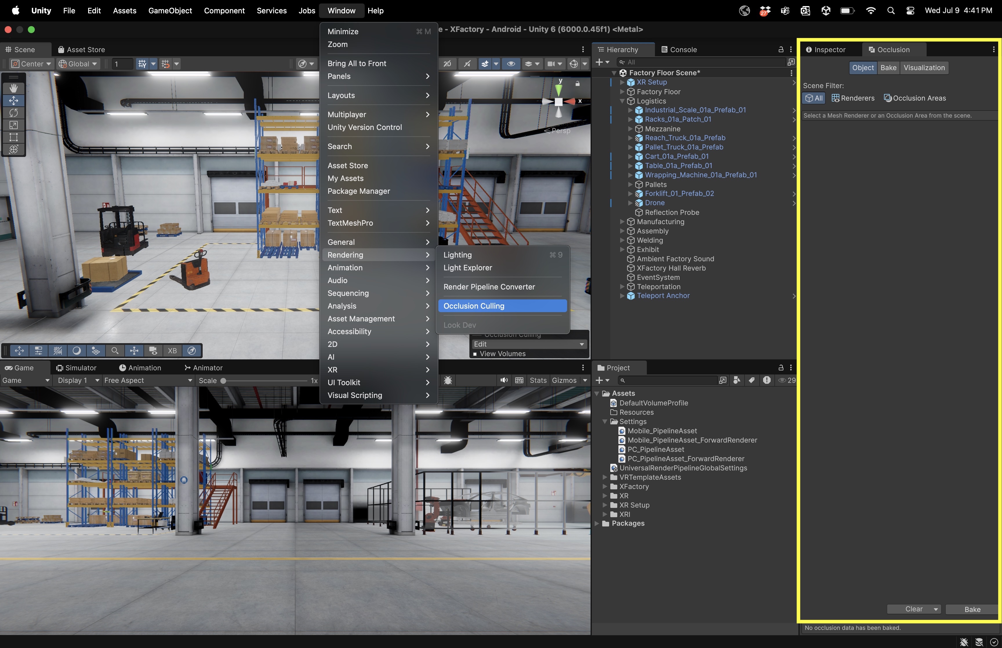
-
Lightmapping: Use
Baked Lightingfor static geometry andMixed LightingwithShadowmaskfor semi-dynamic objects. Baked lighting provides high visual fidelity at a fraction of the real-time lighting cost. To generate a lightmap, open theLightingwindow (Window > Rendering > Lighting > Environment), scroll to theLightmapping Settingssection, and clickGenerate Lighting. Make sure your static objects are marked asLightmap Static, and verify thatBaked Global Illuminationis enabled underMixed Lightingfor successful baking. Do not mark moving or interactive objects as lightmap static.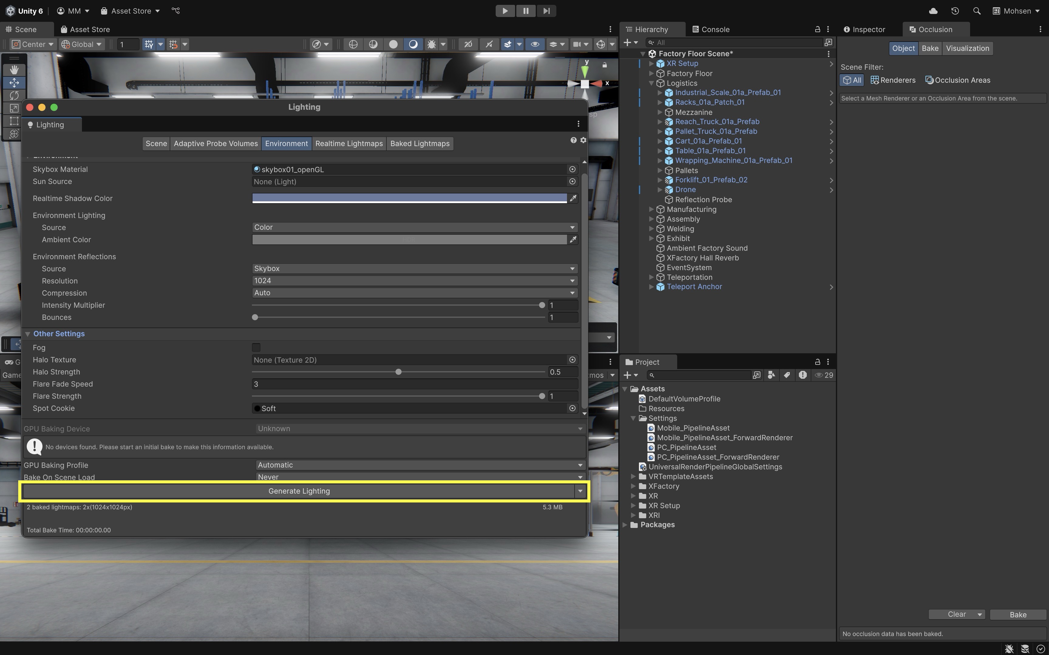
-
Profiler Monitoring: In
Window > Analysis > Profiler, use theRenderingtab to find bottlenecks such asCamera.Render,Shadows.Render, orPostProcessing.Render. Regular use of the Profiler helps catch performance issues early and guides your optimization decisions with real data.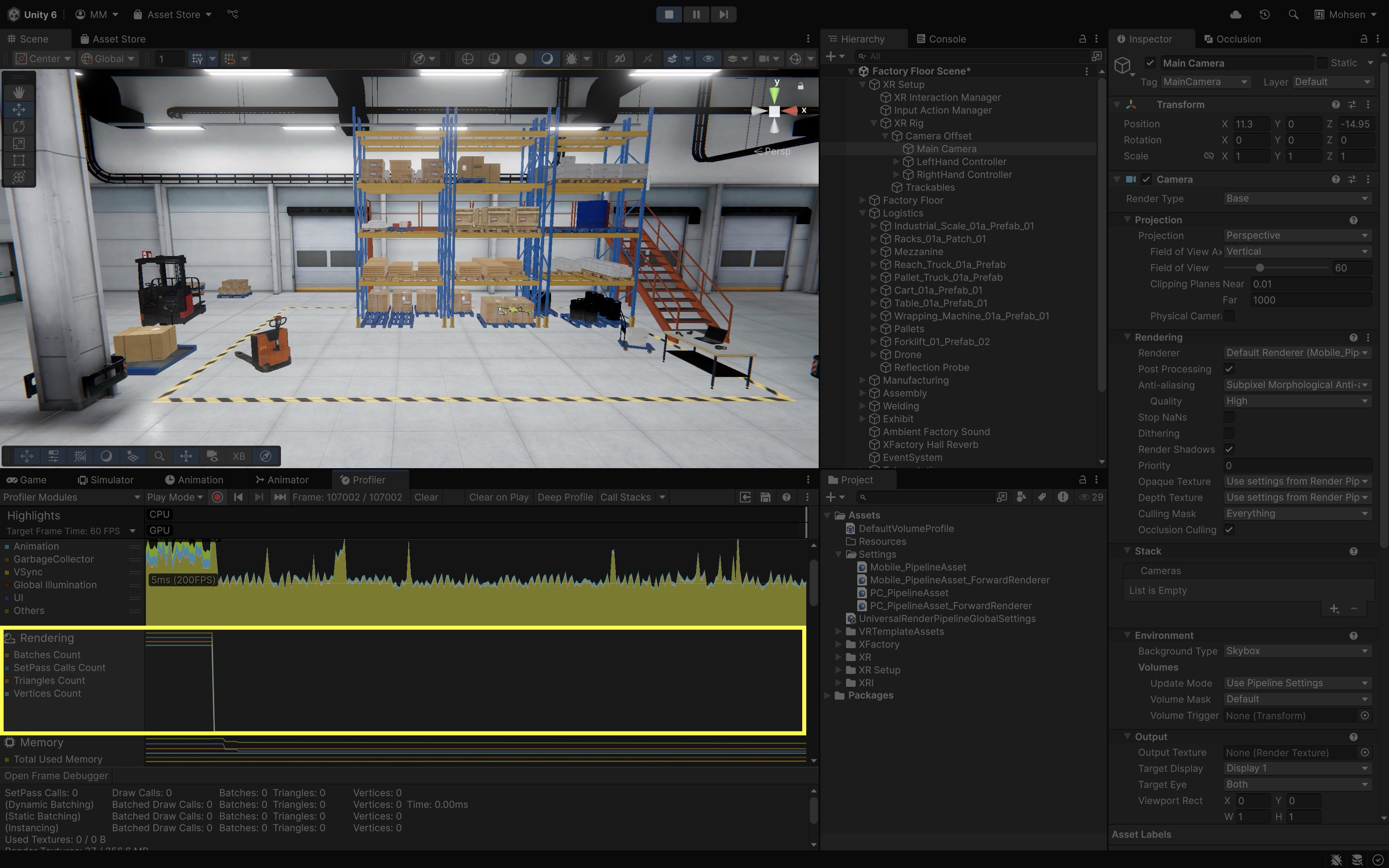
Key Takeaways
- World, local, and camera coordinate systems explain why objects move and rotate the way they do in scene space.
- Proxemics and safety envelopes help place content comfortably and responsibly around industrial equipment.
- Locomotion uses the copied VR Template
XR Origin (XR Rig), XRI Default Input Actions, the Locomotion Mediator, and comfort options such as teleportation and snap turn. - Configure locomotion on the copied template setup in
XFactoryVRbefore adding custom movement logic to avoid conflicting input paths. - Performance work—mesh/texture optimization, batching, and on-device profiling—is part of usable VR navigation.