B3. Physics & Animation

Learning Outcomes
- Explain the role of physics engines in Unity for XR realism. Before class, read about Unity’s physics engines (PhysX vs. Box2D) and explore how they contribute to realistic XR experiences.
- Add and configure a Rigidbody component in Unity. As preparation, open Unity, attach a
Rigidbodyto a GameObject, and test settings likeUse Gravity,Is Kinematic, andMassto see their effects in play mode.- Identify and use different collider types in Unity. Ahead of the session, review collider types, attach one to a primitive shape, and toggle
Is Triggerto compare collision detection with trigger events.- Create and apply Physics Materials to modify object interactions. In advance, learn about properties like
Dynamic FrictionandBounciness, then create aPhysics Materialand apply it to a GameObject to see how movement and surface response change.- Set up and experiment with joints in Unity. For your prep work, review hinge and fixed joints, then connect two GameObjects with a
Hinge Jointto observe how they behave under gravity.- Describe the basics of animating GameObjects in Unity. Prior to class, review animation terminology and the
Animationwindow to get familiar with keyframes, clips, and controllers.- Create a simple hover animation using the Animation window. Before arriving, review how keyframes control a GameObject’s position, then animate a drone or simple object so it floats up and down smoothly and loops seamlessly.
- Design and use an Animator Controller to manage state transitions. As a pre-class exercise, create an
Animator Controllerfor an animated object and set up a parameter-driven transition, such asHover → MoveForwardorIdle → Active.- Import external animations into Unity. In preparation, review the process for importing
.FBXanimations from tools like Blender or Maya, then practice importing one into Unity for use in a scene.
Physics in Unity
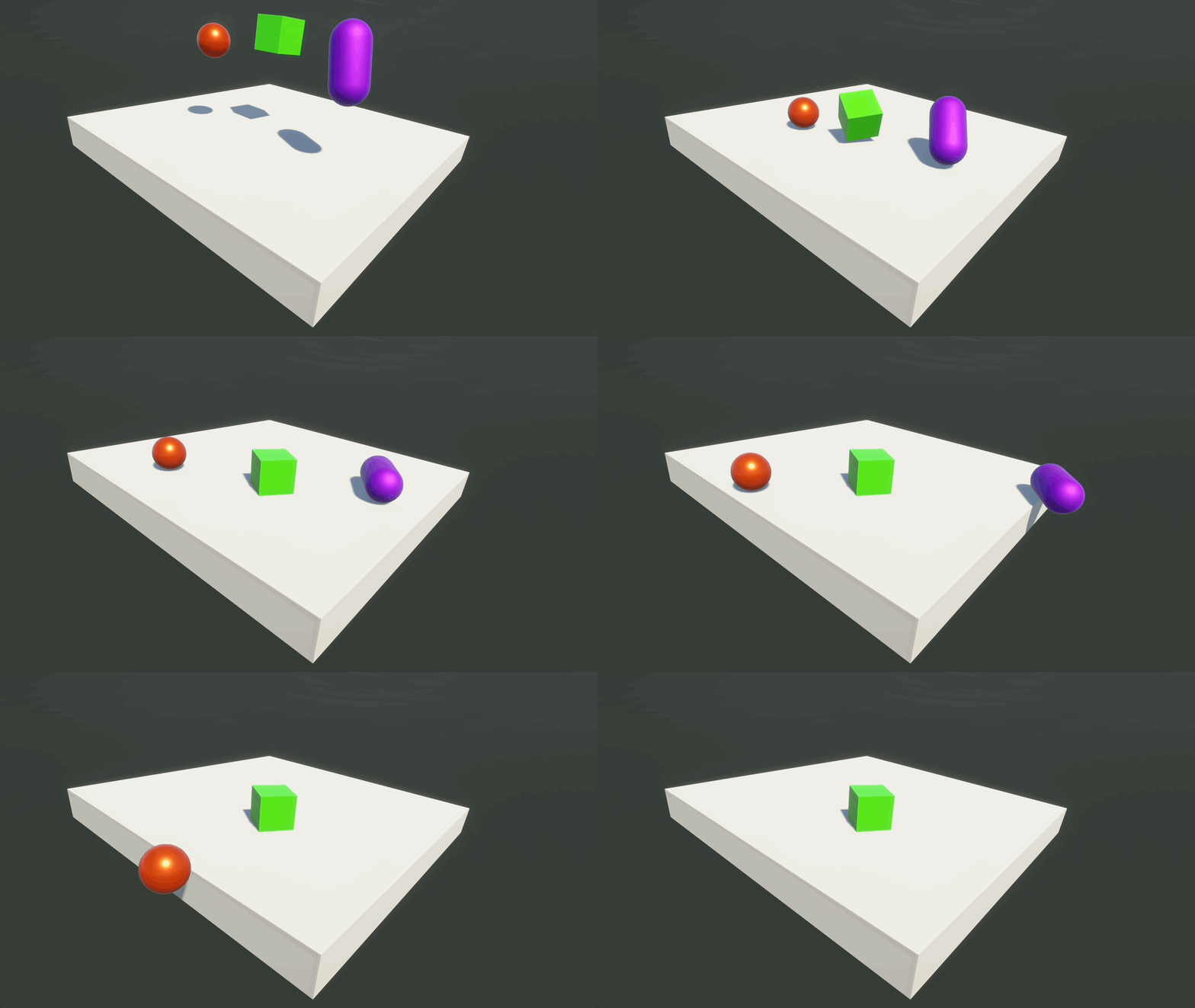
Unity’s built-in 3D physics system enables objects to interact realistically using physical principles such as gravity, collisions, force, motion, and constraints. These mechanics are fundamental to developing engineering simulations, digital twins, and real-time system visualizations, especially when modeling equipment behavior or human-machine interactions. Physics systems bring immersion, realism, and interactivity to XR. Unity physics runs on a fixed timestep, separate from the visual frame rate. This is why physics-related scripting is often placed in FixedUpdate, while visual or input logic commonly uses Update. In XR, stable physics timing matters because jittery or unstable object motion can reduce comfort and realism. Yet, too many active rigidbodies, complex mesh colliders, high-frequency collision checks, or unstable joints can reduce frame rate. Core physics features in Unity include:
- Rigidbody Physics: Applies physics-based behavior to GameObjects using
Rigidbodycomponents, allowing for gravity, forces, torque, and momentum. Common in any dynamic object interaction, such as rolling balls, falling crates, or physics-based puzzles. Enables real-time interaction by allowing objects to respond naturally to user input, such as grabbing, throwing, or pushing. - Collision: Uses
Collidercomponents to detect and configure collisions between GameObjects, supporting both physical and trigger interactions. Essential for environment interaction, player movement boundaries, and hit detection. Provides spatial awareness by ensuring accurate collisions and object placement, which is critical in training and simulation apps. - Character Control: Configures physics-based control systems for first-person and third-person characters, enabling realistic movement and interaction. Ideal for player-controlled avatars in action, adventure, and simulation games. Supports immersion by ensuring player movement and interaction feel natural, enhancing presence in virtual environments.
- Joints: Connects GameObjects using joints to simulate physical behaviors such as pivoting, movement constraints, and mechanical linkages. Useful in building systems like swinging doors, suspension bridges, or robotic arms. Supports human-machine interface simulation by modeling levers, cranks, and other mechanical devices realistically.
- Articulations: Use
ArticulationBodycomponents for more advanced joint chains and reduced-coordinate physics, especially in robotics, industrial machinery, and digital-twin simulations where stable articulated motion is important. Articulations are more advanced than standard joints and are usually introduced only when a project needs robotics-style precision. - Cloth: Simulates fabric behavior for character clothing, flags, curtains, and other dynamic textiles in real-time. Adds realism to clothing and decorative elements in characters and environments. Enhances immersion by reinforcing believability through realistic environmental details.
- Multi-Scene Physics: Manages and simulates separate physics contexts across multiple scenes in a single project, useful for layered or modular level design. Enables complex simulation setups like multiplayer environments or split gameplay areas. Useful for advanced training environments where spatial awareness and multiple concurrent simulations are required.
- Physics Profiler Module: Analyzes and monitors physics performance metrics in your application to identify and resolve bottlenecks. Critical for optimizing physics-heavy scenes and maintaining smooth frame rates on target hardware. Ensures reliable performance in real-time interaction scenarios and robotics simulations.
In Unity physics, distinguish between static colliders (objects that do not move, such as floors and walls), dynamic rigidbodies (objects controlled by physics), and kinematic rigidbodies (objects moved by scripts or animation but still able to interact with dynamic objects in controlled ways). Unity uses NVIDIA PhysX for its built-in 3D physics simulation, including rigidbodies, colliders, collision detection, joints, and many physical interactions. Unity uses Box2D for 2D physics, which is separate from the 3D physics system and uses components such as
Rigidbody2DandCollider2D. For this course, most engineering/XR examples use Unity’s built-in 3D physics system.
Rigidbody
A Rigidbody component allows a GameObject to participate in Unity’s 3D physics simulation. It can respond to gravity, forces, torque, collisions, joints, and constraints. A Rigidbody is different from a Rigidbody2D, which belongs to Unity’s separate 2D physics system. The Rigidbody component makes a GameObject responsive to:
- Gravity: The natural force pulling objects downwards
- External and Internal Forces: A push or pull on an object (e.g., propulsion)
- Collisions: Interactions between physical objects with contact
- Joints and Mechanical Constraints: Restrictions on movement or rotation
Rigidbody Properties
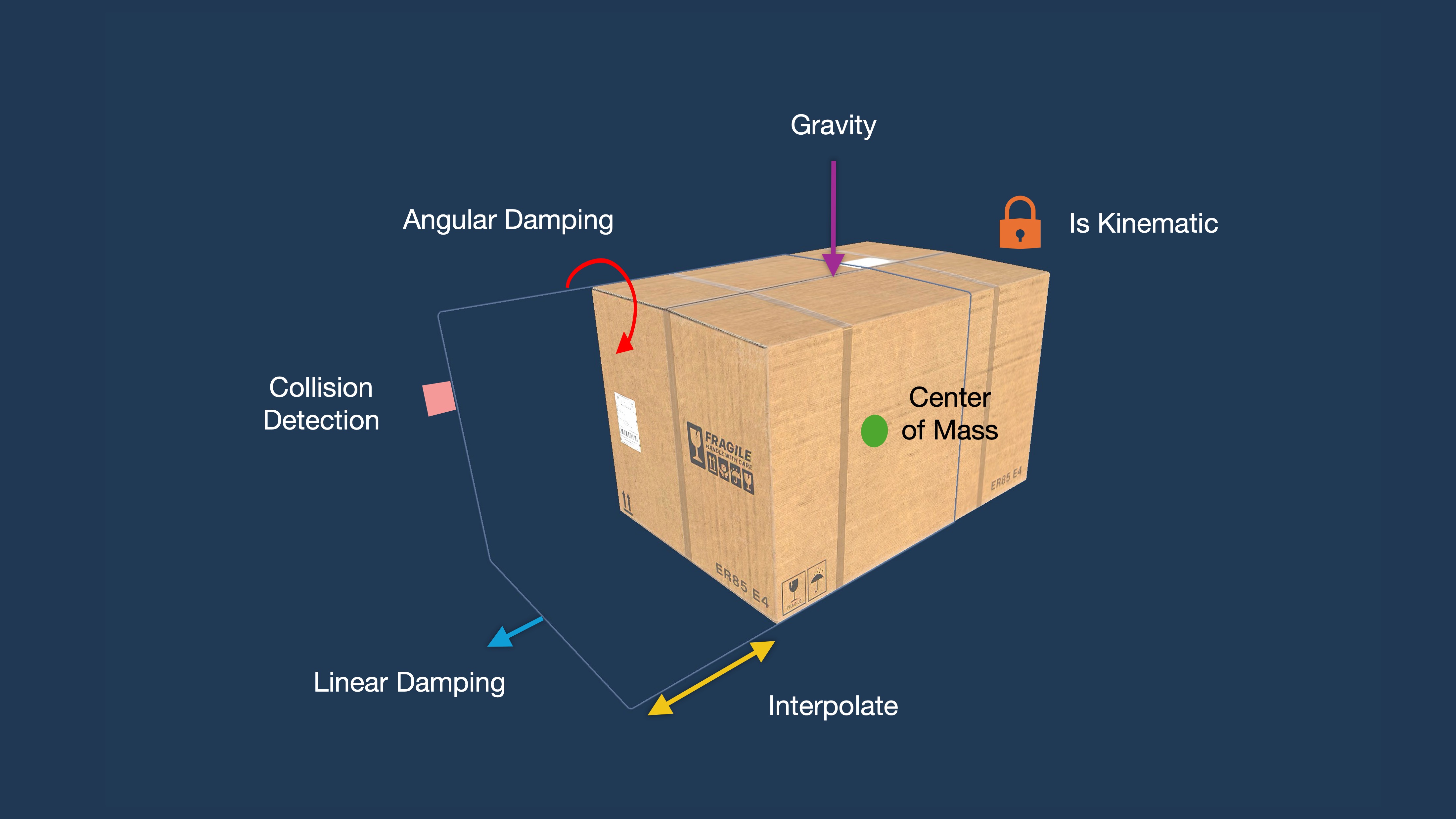
Mass: Determines how resistant the object is to forces (F = ma, where m is mass).Linear Damping: Simulates resistance to linear velocity, such as air resistance or general slowdown. It is calledDragin older Unity versions. This is not the same as contact friction, which is controlled by Physics Materials.Angular Damping: Simulates resistance to rotational velocity. It is calledAngular Dragin older Unity versions.Automatic Center of Mass: If enabled, Unity automatically calculates the object’s center of mass from its collider shapes. Disabling allows you to set a custom center—useful for asymmetrical objects.Automatic Tensor: Controls whether Unity auto-calculates the inertia tensor (rotational mass distribution). Turn off to manually adjust inertia for advanced simulations like flywheels or robotic arms.Use Gravity: Enables the object to fall naturally under simulated gravity.Is Kinematic: If enabled, the Rigidbody is not driven by forces, gravity, or collisions. It should be moved by script or animation. Kinematic rigidbodies are useful for controlled machinery, animated parts, or XR interactables that should follow user input predictably.Interpolate: Smooths position/rotation updates between physics steps (prevents jitter in motion rendering).Collision Detection: Determines how Unity checks for collisions. Continuous modes can reduce tunneling for fast-moving objects, but they are more expensive thanDiscrete.Constraints: Locks position or rotation on specific axes (useful for stability in industrial machines).
Rigidbody Physics Demo
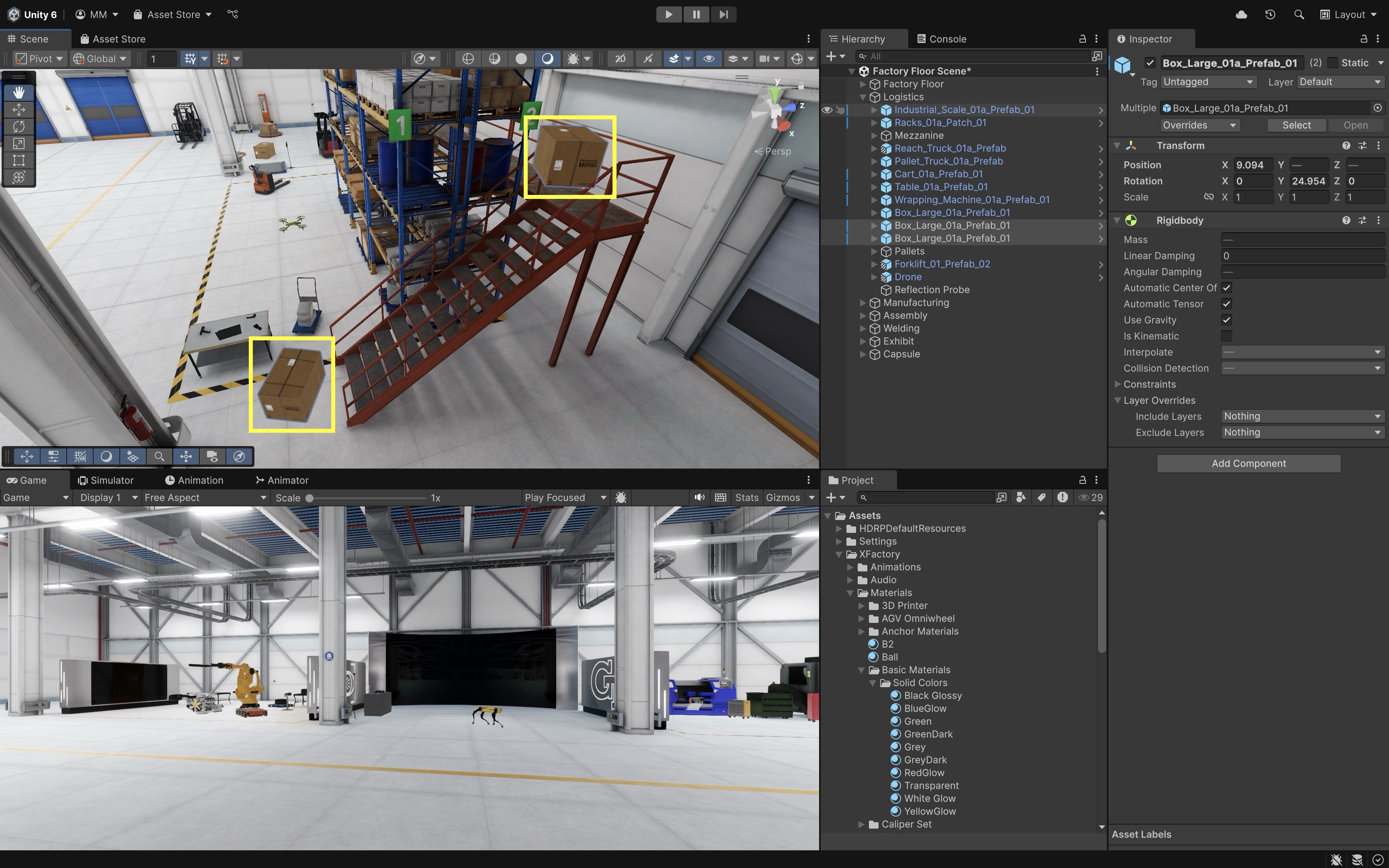
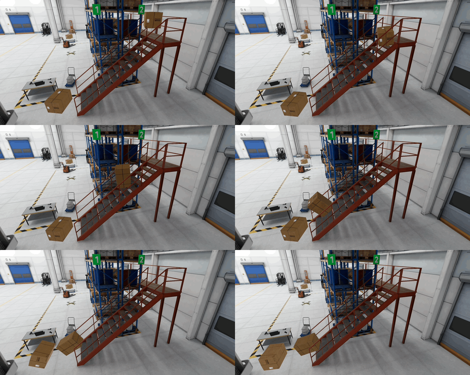
Let’s use the logistics station’s mezzanine to demonstrate the Rigidbody component. Place one storage box (Box_Large_01a_Prefab_01) at the top of the stairs and another at the bottom (make sure the object is not marked as static in the Inspector, since static objects are not intended to move during physics simulation). When the top box falls, it collides with the bottom one. By changing Rigidbody properties one at a time, you’ll see how each parameter affects behavior.
- Add a
Rigidbody:- Select the top box.
- In the
Inspector, clickAdd Componentand selectRigidbody. - Repeat the same for the bottom box so it can react when the top one collides with it.
-
This enables physics-based motion so the box can fall and collide naturally.
- Explore
Mass:- Set
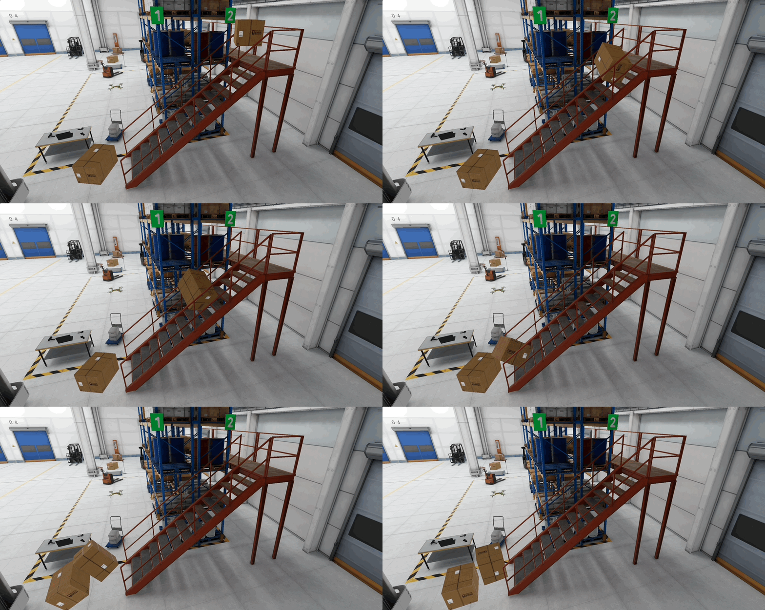
Mass = 1on the top box: it bounces off the bottom box with little effect. -
Set
Mass = 200on the top box: the bottom box is pushed strongly or knocked over.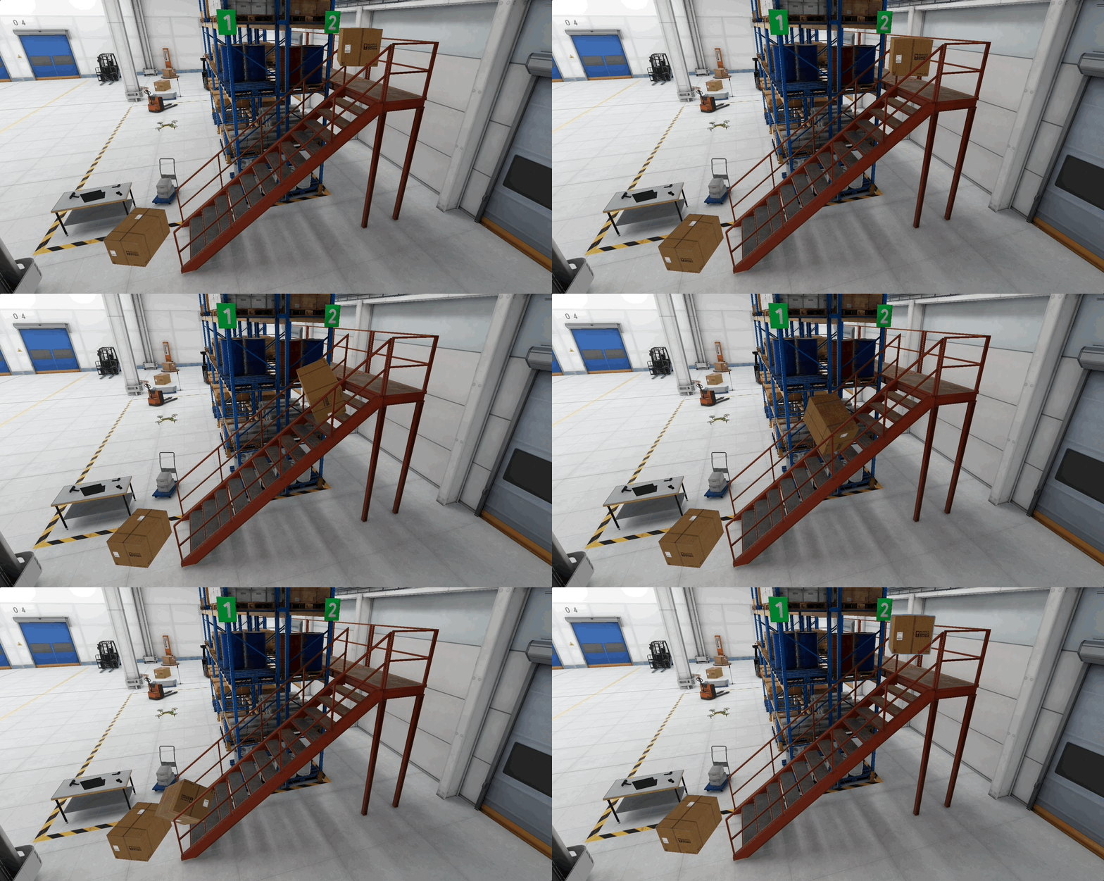
- Swap the
Massvalues and see what happens. Note that mass changes collision impact, but not fall speed.
- Swap the
- Set
- Explore
Linear Damping(Drag):-
Set
Linear Damping = 0: after impact, the top box keeps sliding and may push the bottom box farther. -
Set
Linear Damping = 3: the top box slows down quickly, transferring less motion to the bottom one.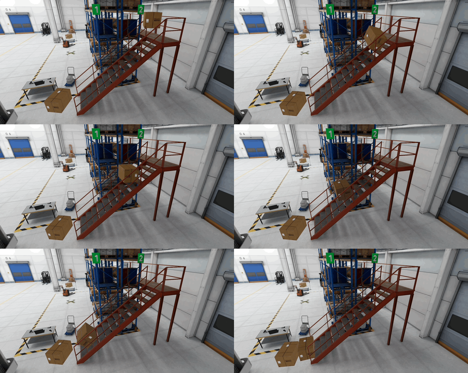
Linear damping is a general resistance to linear velocity, like air resistance or artificial slowdown. Contact friction between surfaces is controlled separately with Physics Materials.
-
- Explore
Angular Damping:-
Set
Angular Damping = 0: the top box spins wildly after hitting, and may topple the bottom box.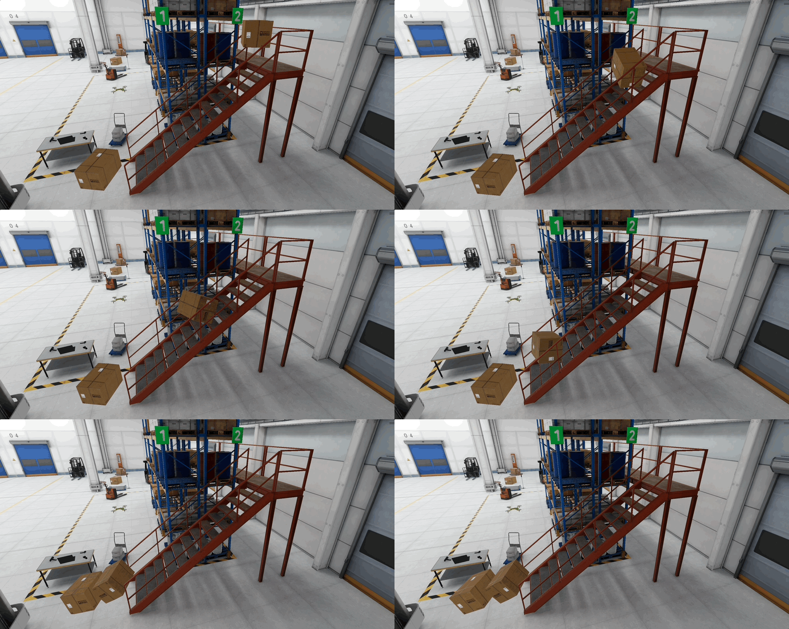
-
Set
Angular Damping = 3: the top box stops spinning quickly, stabilizing the collision.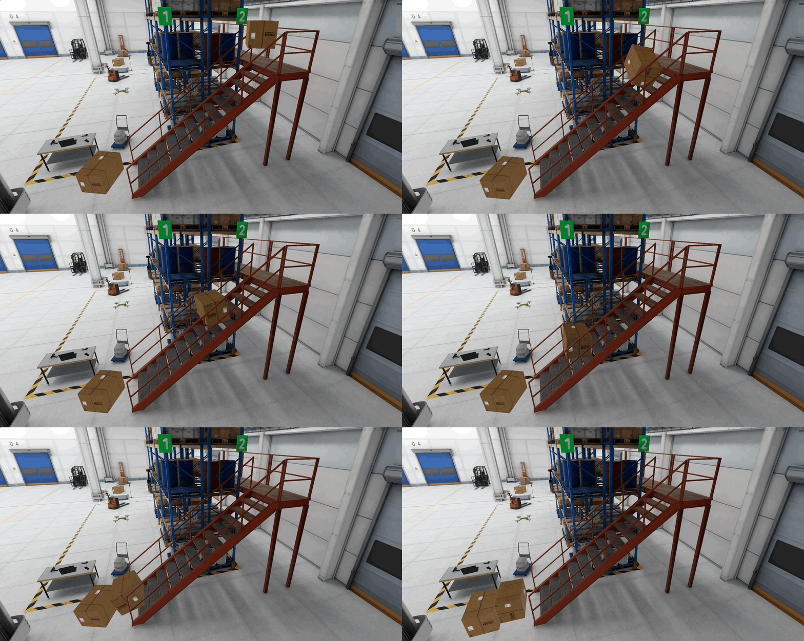
Angular damping simulates resistance to rotation.
-
- Explore
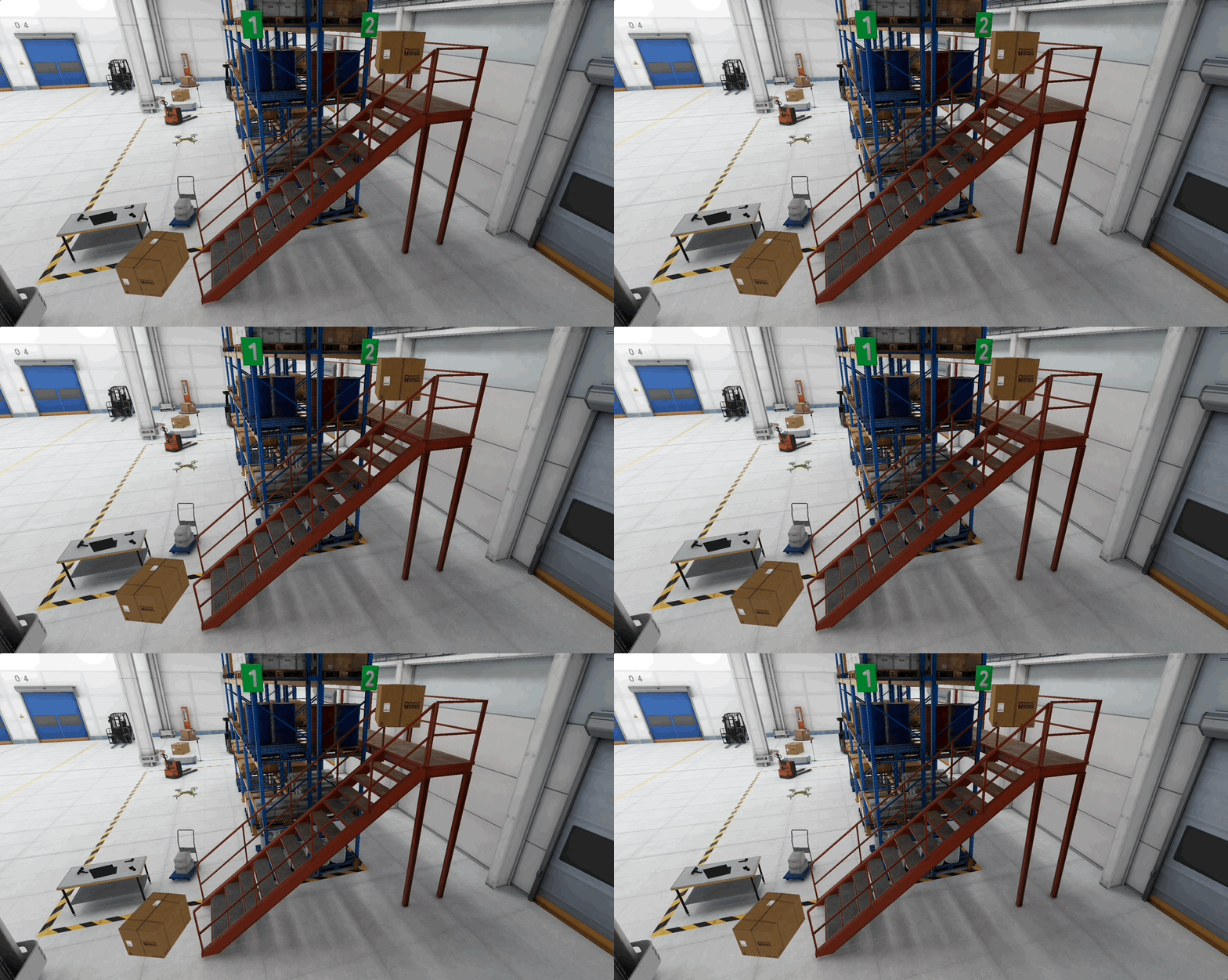
Use Gravity:- Disable
Use Gravity: the top box floats above the stairs and never reaches the bottom box. -
Enable again: it falls naturally and collides. Gravity toggle simulates weightless environments.
- Disable
- Explore
Is Kinematic:- Enable
Is Kinematicon the top box: it no longer falls or pushes the bottom box. - Disable: it collides dynamically and the bottom box reacts.
- Kinematic objects are moved by script or animation rather than by forces or gravity.
- Enable
- Explore
Interpolate:-
Set
Interpolate = None: motion may look jittery when the boxes slide or settle after impact. -
Set
Interpolate = Interpolate: movement looks smoother as they push and collide. Interpolation smooths rendering of physics objects.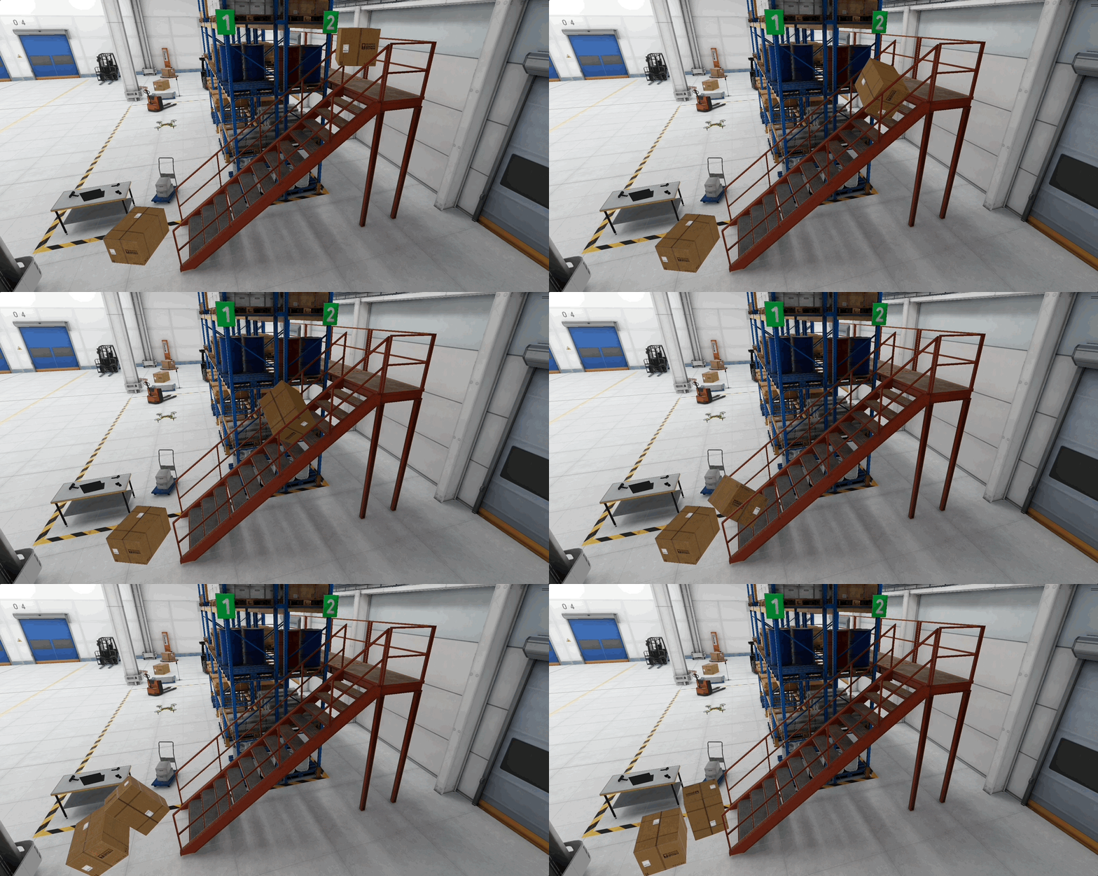
-
- Explore
Collision Detection:-
Set to
Discrete: at high speed, the top box may clip into the bottom box instead of colliding cleanly. -
Set to
Continuous: the collision is always detected and the bottom box reacts correctly. Continuous collision detection helps reduce tunneling in fast-moving objects, but it has a higher performance cost.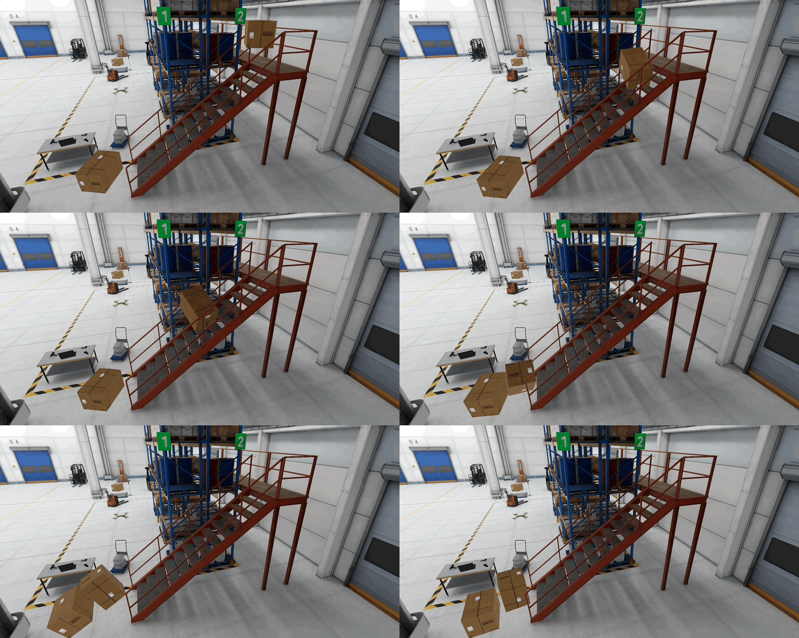
-
- Explore
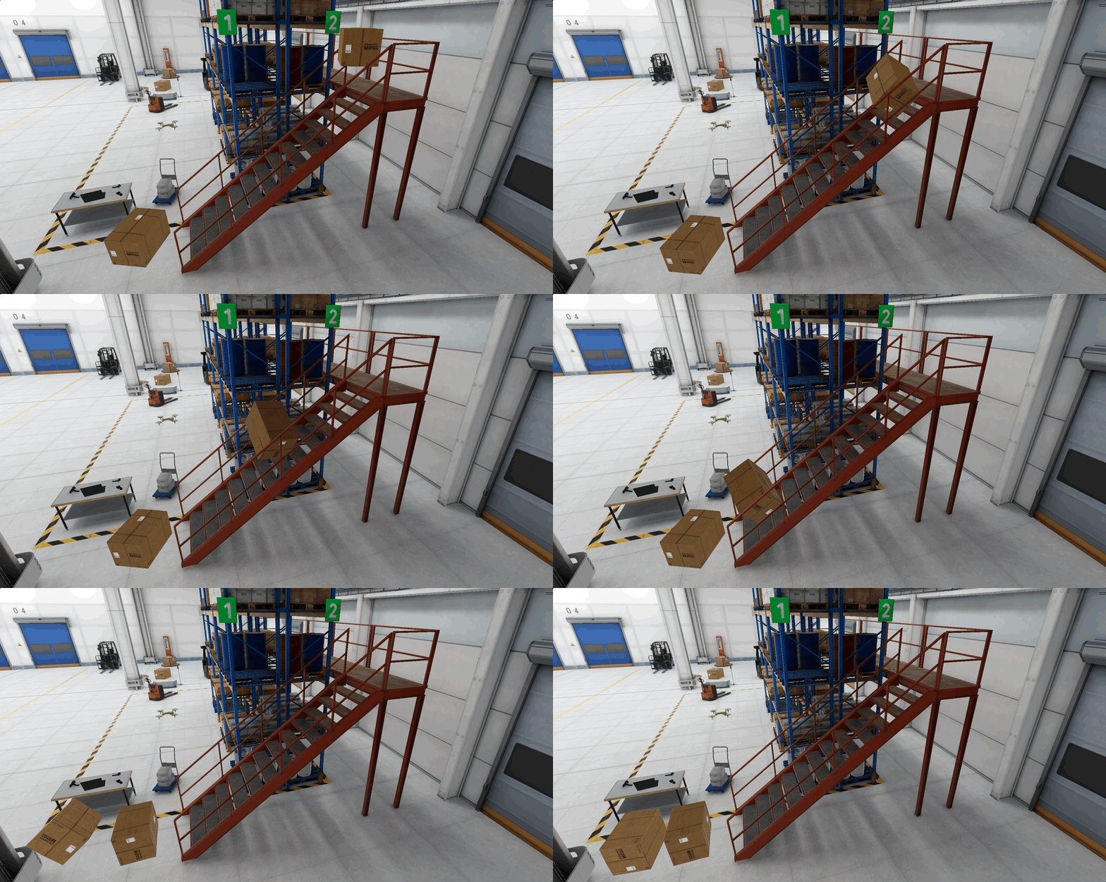
Automatic Center of Mass:- Enabled: the top box lands balanced and pushes the bottom box evenly.
- Disabled + adjust manually (e.g.,
(0.1, 0.4, 0.1)): the top box tips unevenly, applying sideways force to the bottom box. -
This is useful for uneven loads, vehicles, robotics.
- Explore
Automatic Tensor:- Enabled: the top box spins and settles naturally when colliding.
- Disabled + manual adjustments (e.g.,
(1, 2, 1)): the rotation looks unnatural and may knock the bottom box in strange ways. -
This property can be used for advanced simulations, like inertia control for robotics or machinery.
Colliders
A Collider defines an object’s physical boundary for detecting and resolving collisions. It is essential for interactivity in XR simulations. Colliders don’t cause motion; they only define space for collision detection (when and where objects make contact). They can be either primitive shapes (like boxes, spheres, capsules) for performance or mesh-based for more accurate representations. Colliders can also be set as triggers to detect overlap events without physically blocking movement. For physical collision response, at least one of the interacting objects usually needs a Rigidbody. Triggers detect overlap events without physically blocking motion, but they still require scripting to respond to OnTriggerEnter, OnTriggerStay, or OnTriggerExit.
Types of Colliders
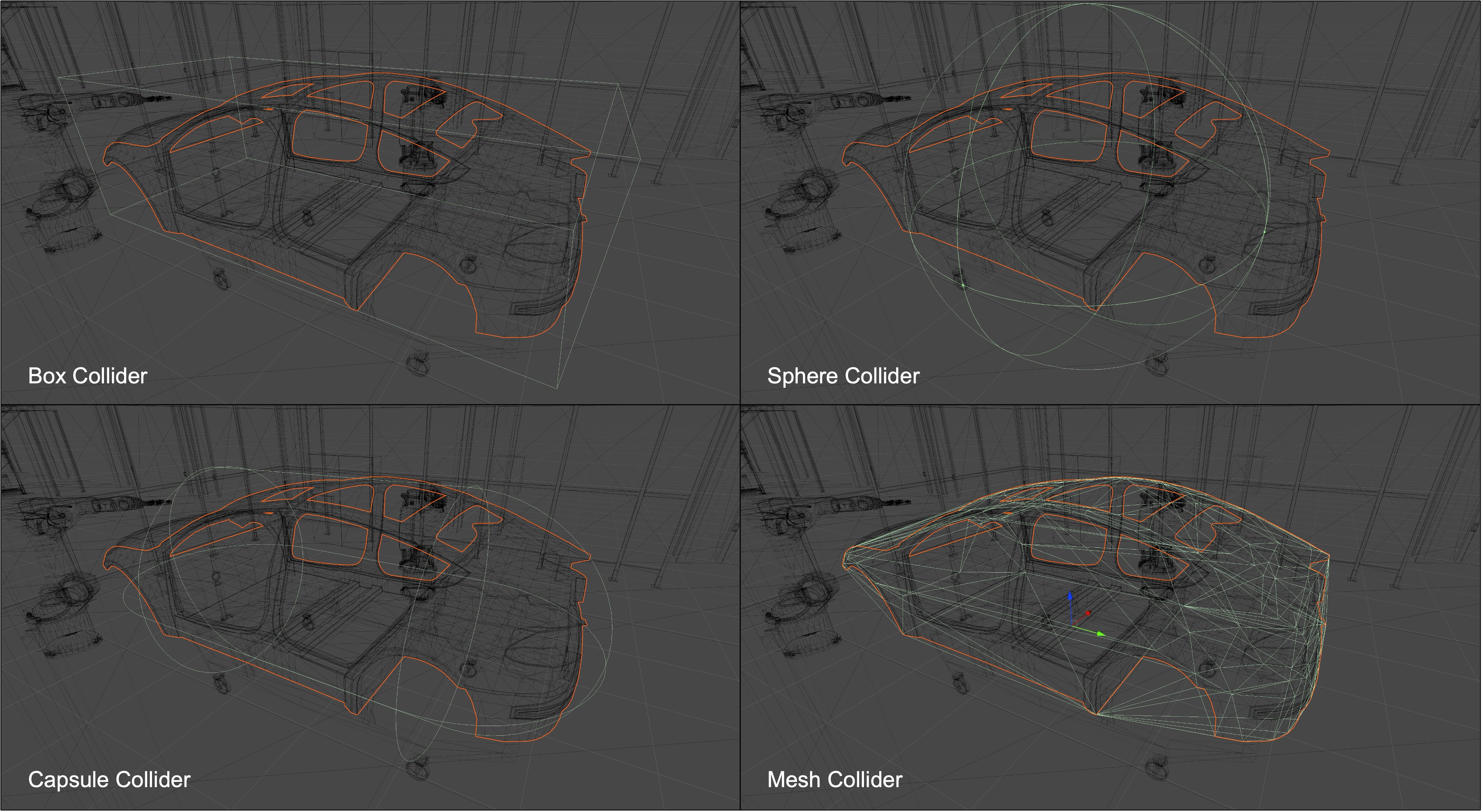
Box Collider: A cuboid (rectangular prism) boundary used for boxy or regular-shaped objects. In XFactory, this is ideal for simulating crates, pallets, racks, or the forklift body where clean, flat surfaces define the object’s shape.Sphere Collider: A spherical boundary used for round or symmetrical objects. Useful in XFactory for parts like robotic ball joints, spherical sensor modules, or small scanning devices dropped from drones.Capsule Collider: A cylindrical collider with rounded ends, well-suited for elongated or humanoid shapes. In XFactory, apply it to mobile drone bodies or the quadruped robot’s legs to model their streamlined movement.Mesh Collider: Uses mesh geometry for detailed collision detection. In XFactory, Mesh Colliders can be useful for complex static machinery such as CNC machines, 3D printers, or car-body fixtures. For moving objects withRigidbody, mesh colliders generally need to be Convex, which simplifies the shape and may not match every detail. Use primitive or compound colliders when possible for performance.Terrain Collider: A collider specialized for large, natural or irregular ground surfaces created with Unity’s Terrain system. This is useful in XFactory’s exterior scene to simulate the factory yard, roads, or loading zones with varied terrain elevation.
For complex engineering objects, prefer compound colliders—several simple colliders arranged on one object hierarchy—before using expensive mesh colliders. Compound colliders often provide a better balance of accuracy and performance.
Adding a Collider
Now, let’s simulate the barcode scanner in the XFactory logistics station falling onto the table. This demonstrates how Unity’s physics system handles collisions using different collider types, and how collider choice affects realism and performance.
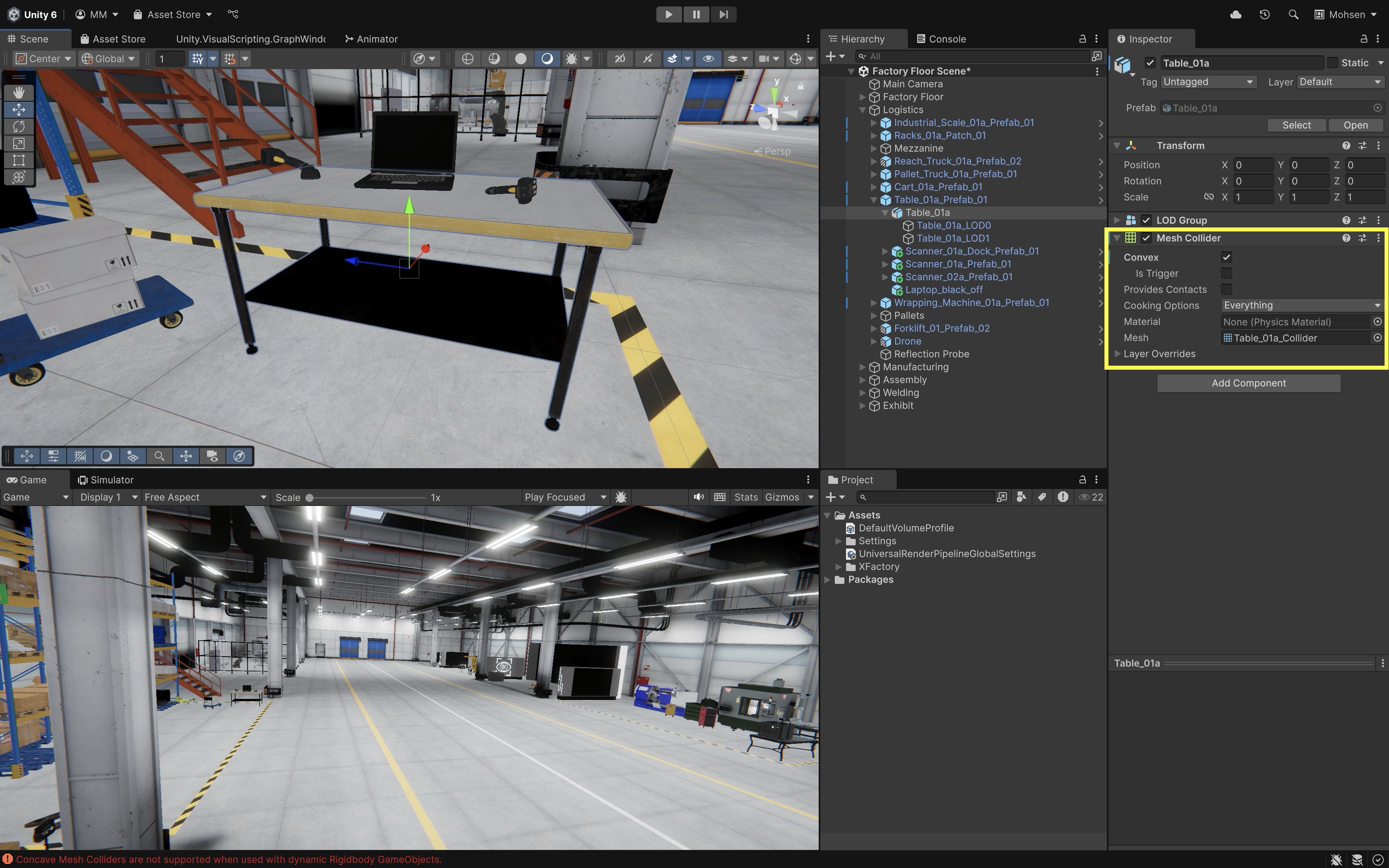
- Use the Table as Ground for the Scanner:
- In the
Hierarchy, locate the table object already present in the scene (e.g.,Table_01a). - Ensure the table has a
Box ColliderorMesh Collidercomponent. - If it’s missing, add one via
Inspector > Add Component > Box Collideror> Mesh Collider. - This acts as the flat surface the scanner will land on, simulating a physical tabletop.
- In the
- Prepare the Barcode Scanner:
- In the
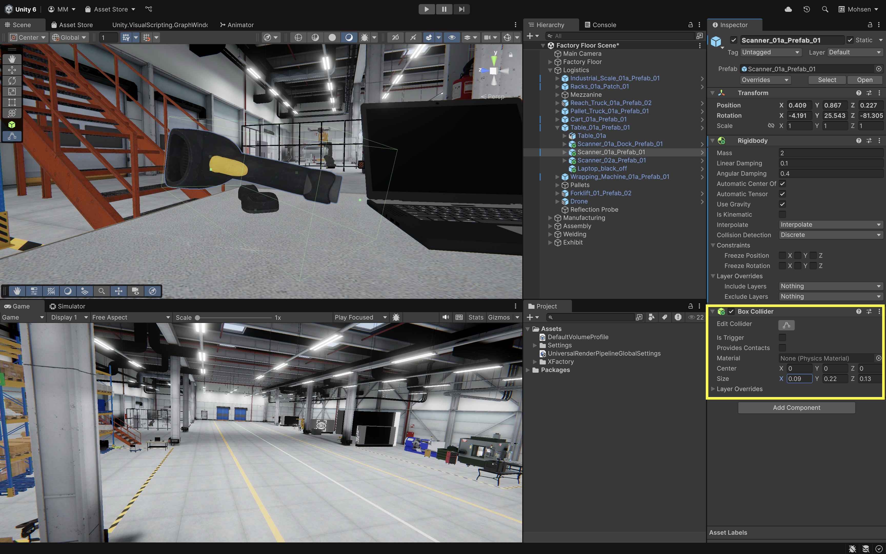
Hierarchy, locate the barcode scanner object (e.g.,Scanner_01a_Prefab_01), which should already be positioned above the table. - Add a
Rigidbodycomponent to the barcode scanner. - Set
Mass = 2(represents a lightweight handheld scanner). - Set
Linear Damping = 0.1andAngular Damping = 0.4(adds light air resistance and rotational stability). - Set
Use Gravity = EnabledandInterpolate = Interpolate.
- In the
- Add a
Box Colliderto the Barcode Scanner:- Select the barcode scanner in the
Hierarchy. - Add a
Box ColliderviaInspector > Add Component > Box Collider. This approach is fast and efficient, but less accurate for non-boxy shapes. It is useful for general physics approximations.
- Select the barcode scanner in the
- Add a
Mesh Colliderto the Barcode Scanner:- Remove the
Box Colliderfrom the barcode scanner. - Add a
Mesh Collider. In theInspector, enableConvexto allow physics simulation with theRigidbody. This approach closely matches the scanner’s shape but can be more performance-intensive.
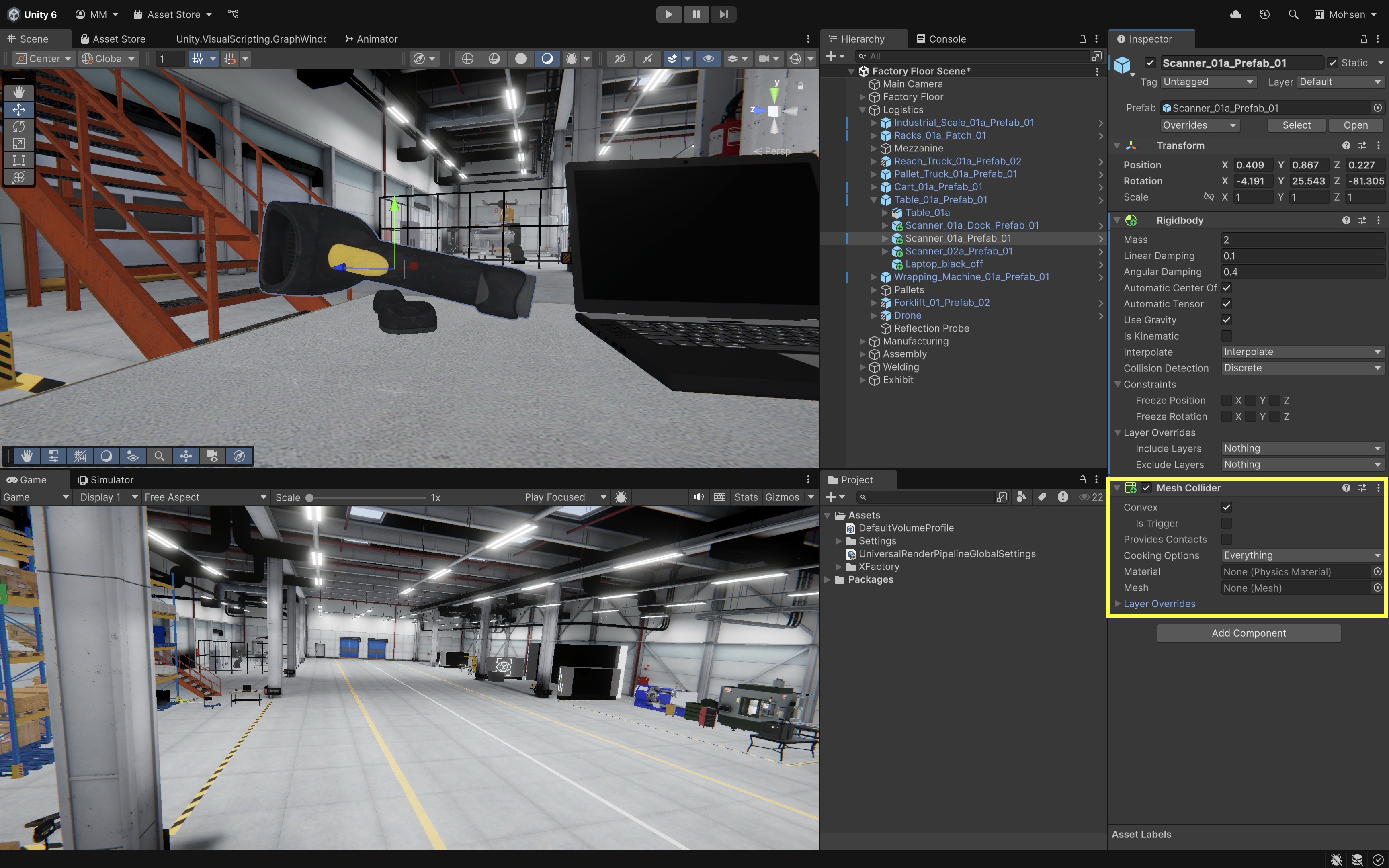
The
Convexcheckbox in aMesh Colliderforces Unity to approximate the mesh with a simplified convex shape (no holes or inward curves). This makes physics calculations faster and is required if the object has aRigidbodyand needs to move. - Remove the
- Run the Scene:
- Press
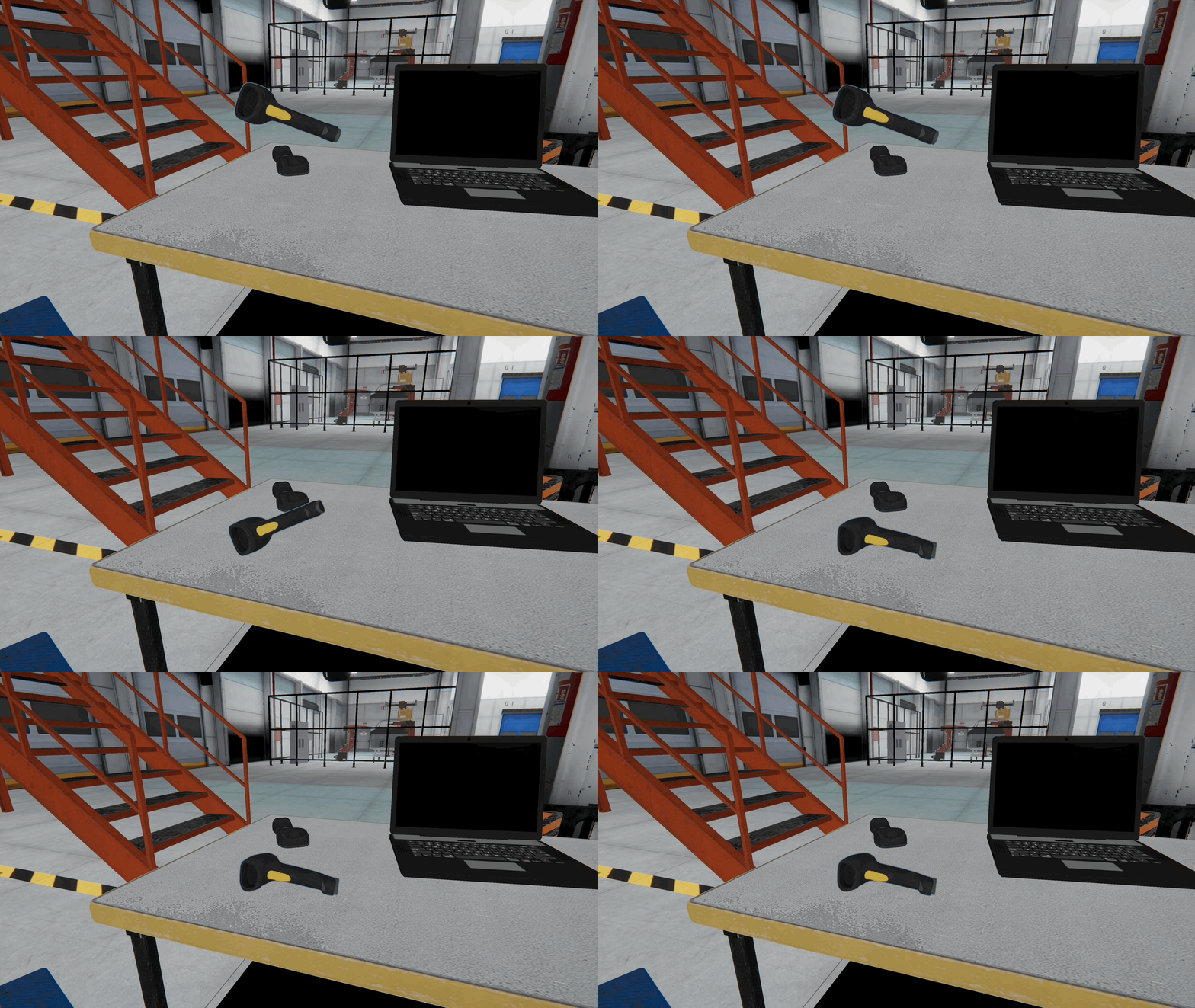
Playto simulate. - Watch as the barcode scanner falls from its elevated position and collides with the tabletop.
- Compare the results between the two collider types.
Box Collideris faster, but may not align perfectly with the scanner’s geometry.Mesh Collidercan provide more precise collision boundaries, but it usually has higher processing overhead—especially in large-scale scenes or when used on moving objects.- The same fall can be previewed in a Quest Link–connected Meta Quest headset before Module D covers VR interaction.
Is Trigger(a checkbox in theCollidercomponent) enables an object to detect when something enters, exits, or stays within its collider without physically interacting (no collision force is applied). Use this for non-physical detection systems—for example, when a box passes into a scanner area at the logistics station, triggering inventory logging or sensor activation in a digital twin simulation. - Press
Character Controller
The Character Controller is a specialized capsule-shaped controller for player movement. Unlike a dynamic Rigidbody, it is not moved by forces or gravity automatically. Instead, scripts move it directly while it still detects collisions with the environment. This makes it useful for first-person or third-person navigation prototypes. For XR locomotion, Unity’s XR Interaction Toolkit will usually provide the main locomotion components later in the course, but the Character Controller is still useful for understanding non-XR navigation. Follow the tutorial below to set up a Character Controller in XFactory. Don’t worry about understanding the script just yet—we will cover scripting in detail later in Module C.
- Set Up the Player:
- Right-click on the
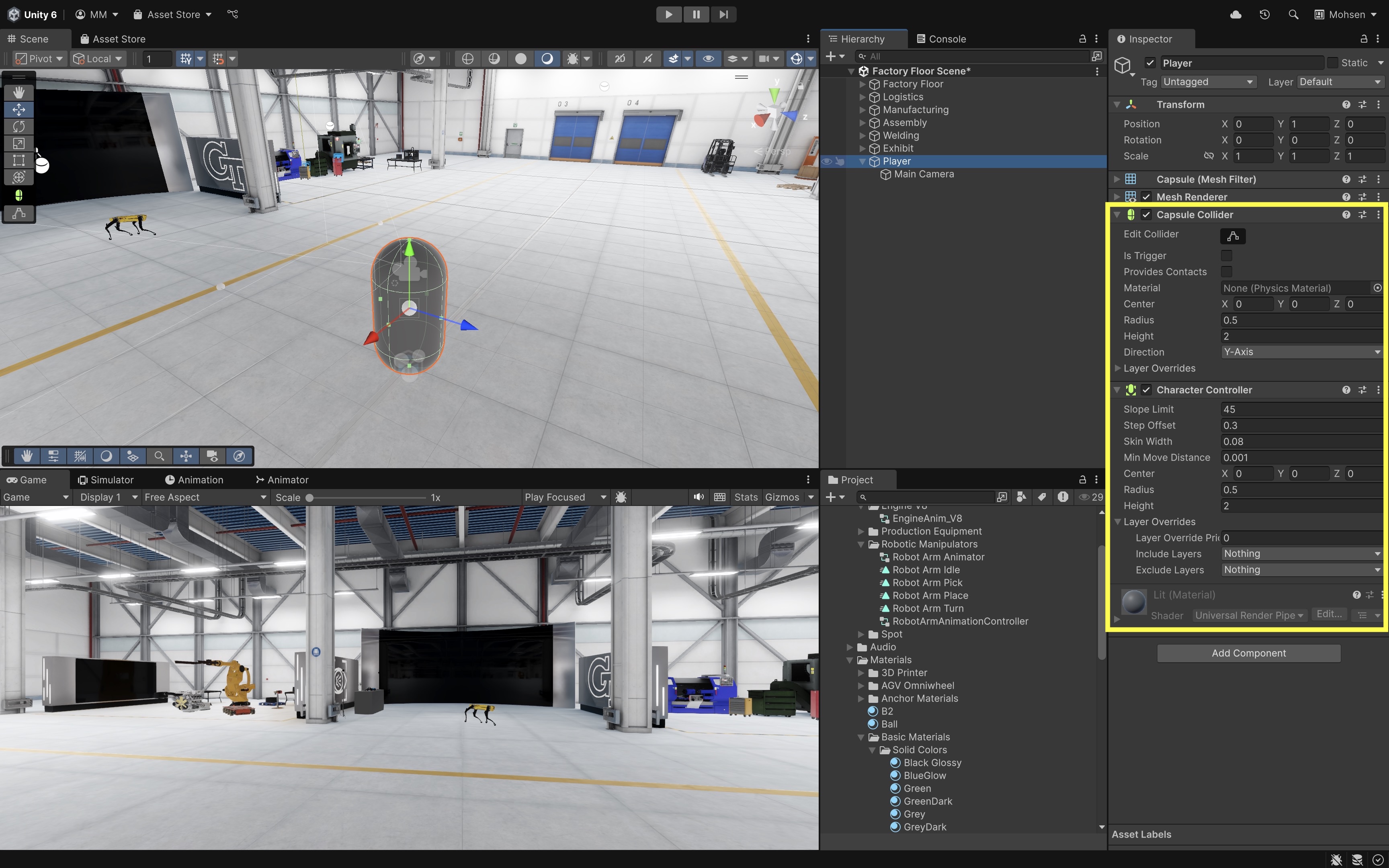
Hierarchyand select3D Object > Capsule. Rename itPlayer. - Add a
Character Controllercomponent usingInspector > Add Component > Character Controller. - Drag the
Main Camerainside thePlayerobject and move it to the top of the capsule (aroundY = 1.6).
- Right-click on the
- Add a Movement Script:
- Right-click in the
Projectwindow and create a new C# script or MonoBehaviour script. In Unity 6, this may appear underCreate > Scripting > MonoBehaviour Scriptdepending on the project template and editor layout. - Name it
PlayerController.cs. Attach it toPlayerby dragging and dropping it into itsInspector. - Double-click on the script to open it in your IDE (VS Code or even a simple text editor for now).
This simple script uses Unity’s legacy
Input.GetAxisandInput.GetButtonDownAPIs for beginner readability. If your project is configured for the newer Input System only, enable compatibility with the old Input Manager or adapt the script later when input systems are covered.- Replace the default script with the following:
 using UnityEngine;

 [RequireComponent(typeof(CharacterController))]
 public class PlayerController : MonoBehaviour
 {
     // Movement speed
     public float speed = 5f;

     // Rotation speed for keyboard input
     public float rotationSpeed = 60f;

     // Gravity value
     public float gravity = -9.81f;

     // Jump height
     public float jumpHeight = 1.5f;

     // Reference to the CharacterController component
     private CharacterController controller;

     // Player's current velocity
     private Vector3 velocity;

     // Whether the player is grounded
     private bool isGrounded;

     // Assign Main Camera in Inspector
     public Transform cam;

     // Player's current x rotation
     private float xRotation = 0f;

     void Start()
     {
         // Get the CharacterController component
         controller = GetComponent<CharacterController>();
     }

     void Update()
     {
         // Ground check
         isGrounded = controller.isGrounded;

         if (isGrounded && velocity.y < 0)
             velocity.y = -2f;

         // Movement
         float moveX = Input.GetAxis("Horizontal");
         float moveZ = Input.GetAxis("Vertical");

         Vector3 move = transform.right * moveX +
                       transform.forward * moveZ;

         controller.Move(move * speed * Time.deltaTime);

         // Jump
         if (Input.GetButtonDown("Jump") && isGrounded)
         {
             velocity.y = Mathf.Sqrt(jumpHeight * -2f * gravity);
         }

         // Apply gravity
         velocity.y += gravity * Time.deltaTime;
         controller.Move(velocity * Time.deltaTime);

         // Camera rotation with keys
         float yaw = 0f;
         float pitch = 0f;

         if (Input.GetKey(KeyCode.Q)) yaw = -rotationSpeed * Time.deltaTime;
         if (Input.GetKey(KeyCode.E)) yaw = rotationSpeed * Time.deltaTime;
         if (Input.GetKey(KeyCode.Z)) pitch = -rotationSpeed * Time.deltaTime;
         if (Input.GetKey(KeyCode.C)) pitch = rotationSpeed * Time.deltaTime;

         // Apply yaw (rotate player left/right)
         transform.Rotate(Vector3.up * yaw);

         // Apply pitch (rotate camera up/down)
         xRotation -= pitch;
         xRotation = Mathf.Clamp(xRotation, -90f, 90f);
         cam.localRotation = Quaternion.Euler(xRotation, 0f, 0f);
     }
 }
This tutorial uses Unity’s legacy Input Manager, so if the player does not move, set Edit → Project Settings → Player → Other Settings → Active Input Handling to Both, then restart Unity if prompted.
- Right-click in the
- Hook Up the Camera:
- Click on the
PlayerGameObject to open itsInspector. - Drag the
Main Camerainto the script’sCamfield.
If the script throws an error, make sure the
Camfield is assigned in the Inspector.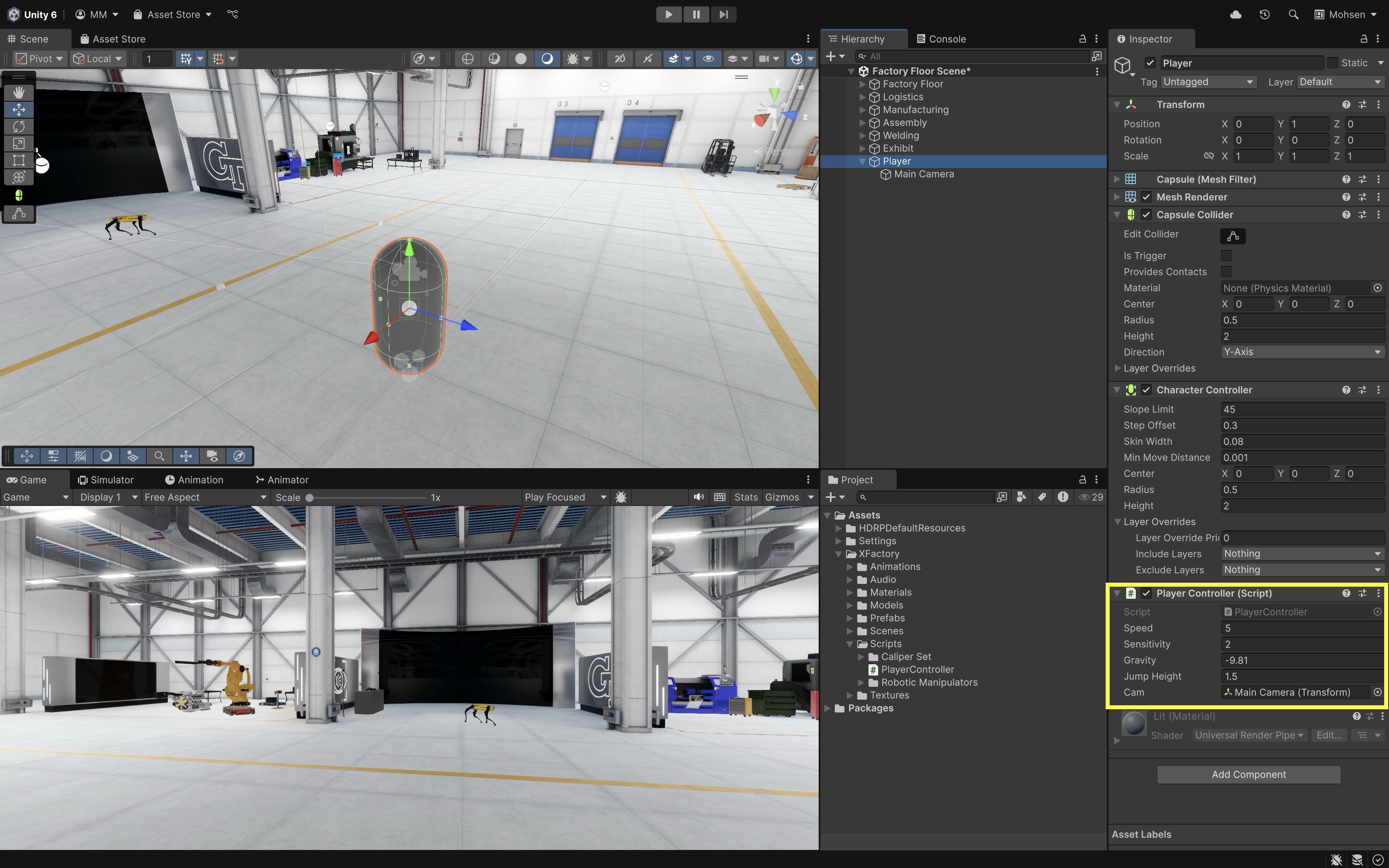
- Click on the
- Play and Test:
- Press Play and test.
- Move with WASD.
- Jump with Space.
- Rotate left/right with Q/E and look up/down with Z/C.
- If Quest Link is set up, you can walk through the scene in your Meta Quest during the same Play Mode test.
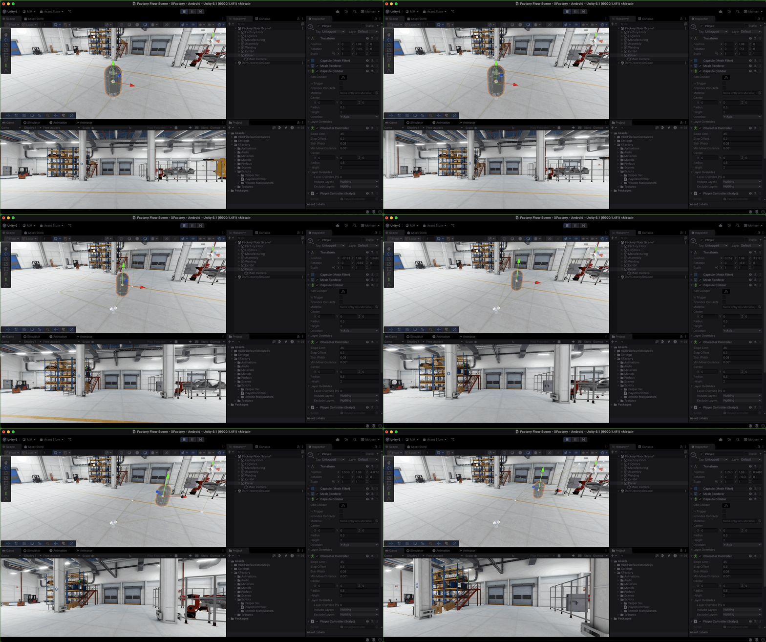
Now you have a simple first-person controller using Unity’s built-in Character Controller and Main Camera.
Physics Materials
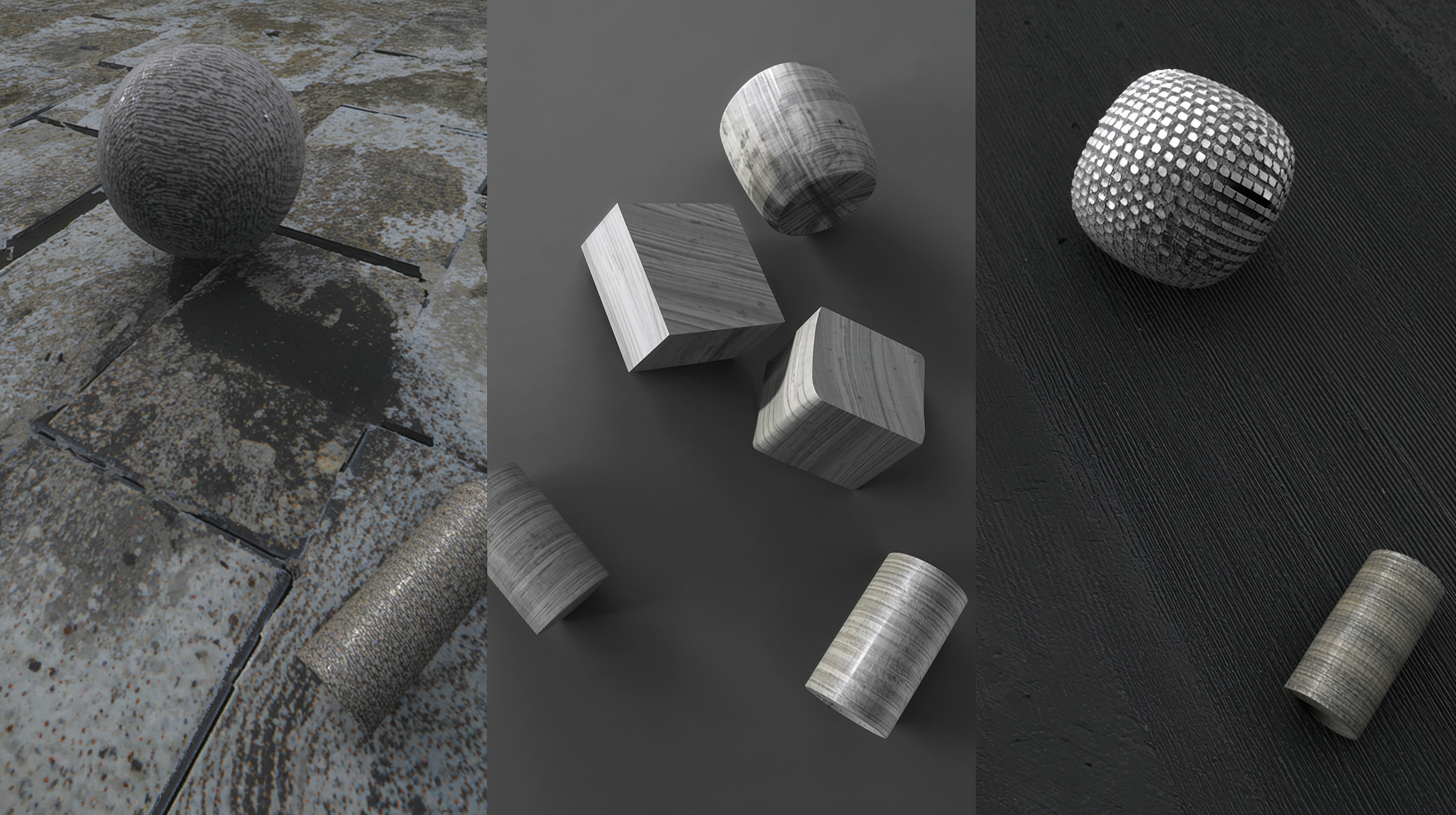
In Unity, a Physics Material controls how collider surfaces behave when they touch, slide, or bounce. Physics Materials are assigned to Collider components and define properties such as dynamic friction, static friction, bounciness, and combine modes. They are useful for simulating slippery floors, rubber tires, rough concrete, or bouncing tools.
Physics Material Properties
Use the following Physics Material properties to fine-tune interactions in simulations where physical realism—such as sliding resistance, bounce-back, or grip—is critical:
Dynamic Friction: Friction applied when an object is already in motion, affecting how easily it slides across a surface and how much force is required to keep it moving (e.g., a forklift’s tire sliding slightly on a smooth concrete floor).Static Friction: Friction that resists the start of movement when an object is at rest, determining how much force is needed to overcome initial inertia (e.g., a crate resisting movement as it is pushed).Bounciness: Controls how much energy is retained after a collision, directly affecting how high or far an object rebounds (e.g., a tire bouncing slightly during a vertical drop).Friction Combine: Defines how friction values from two colliding surfaces are combined—using options likeMinimum,Maximum,Average, orMultiply—to determine the resulting surface interaction (e.g., simulating the contact between a rubber tire and a metal loading ramp).Bounce Combine: Determines how bounciness values from two surfaces are blended during impact, which influences how much an object rebounds (e.g., a plastic tool dropped on the concrete floor).
Physics Materials are approximations for real-time simulation. They are useful for believable behavior, but they should not be treated as precise engineering contact models without validation.
Physics Material Demo
Let’s simulate the tire sitting on a wooden pallet in the assembly station rolling off and bouncing across the floor. This exercise demonstrates how to use a Physics Material to control surface properties like friction and bounciness, simulating realistic motion and impact behavior.
- Locate and Prepare the Tire:
- In the
Hierarchy, locate the tire object already positioned on a wooden pallet in the assembly station (e.g.,TireonPallet_01a). - Ensure the tire has a
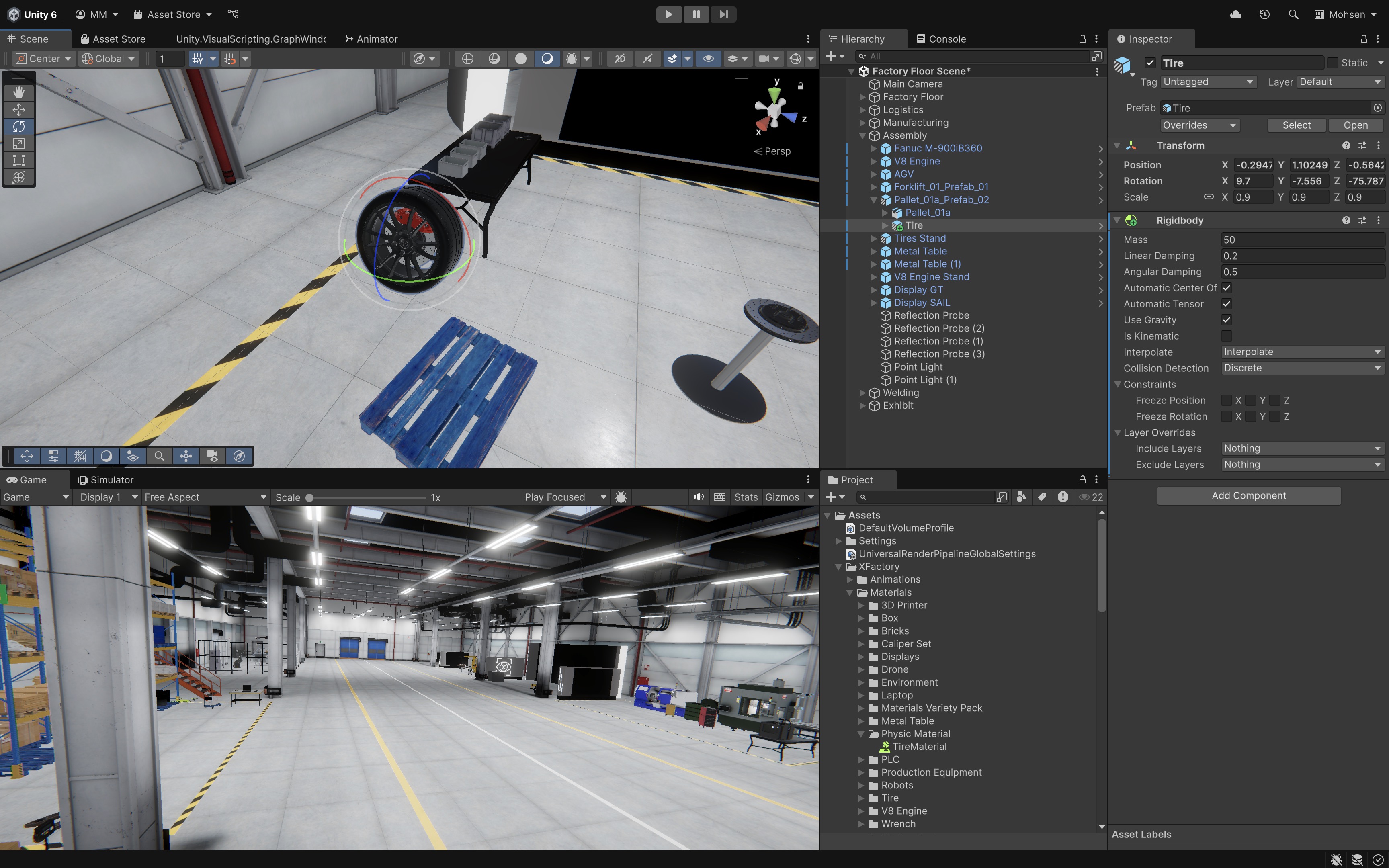
Rigidbodycomponent assigned to its parent GameObject to enable physics simulation. If missing, add it viaInspector > Add Component > Rigidbody. SetMass = 50,Linear Damping = 0.2,Angular Damping = 0.5,Interpolate = Interpolate, andCollision Detection = Discrete. - Add a
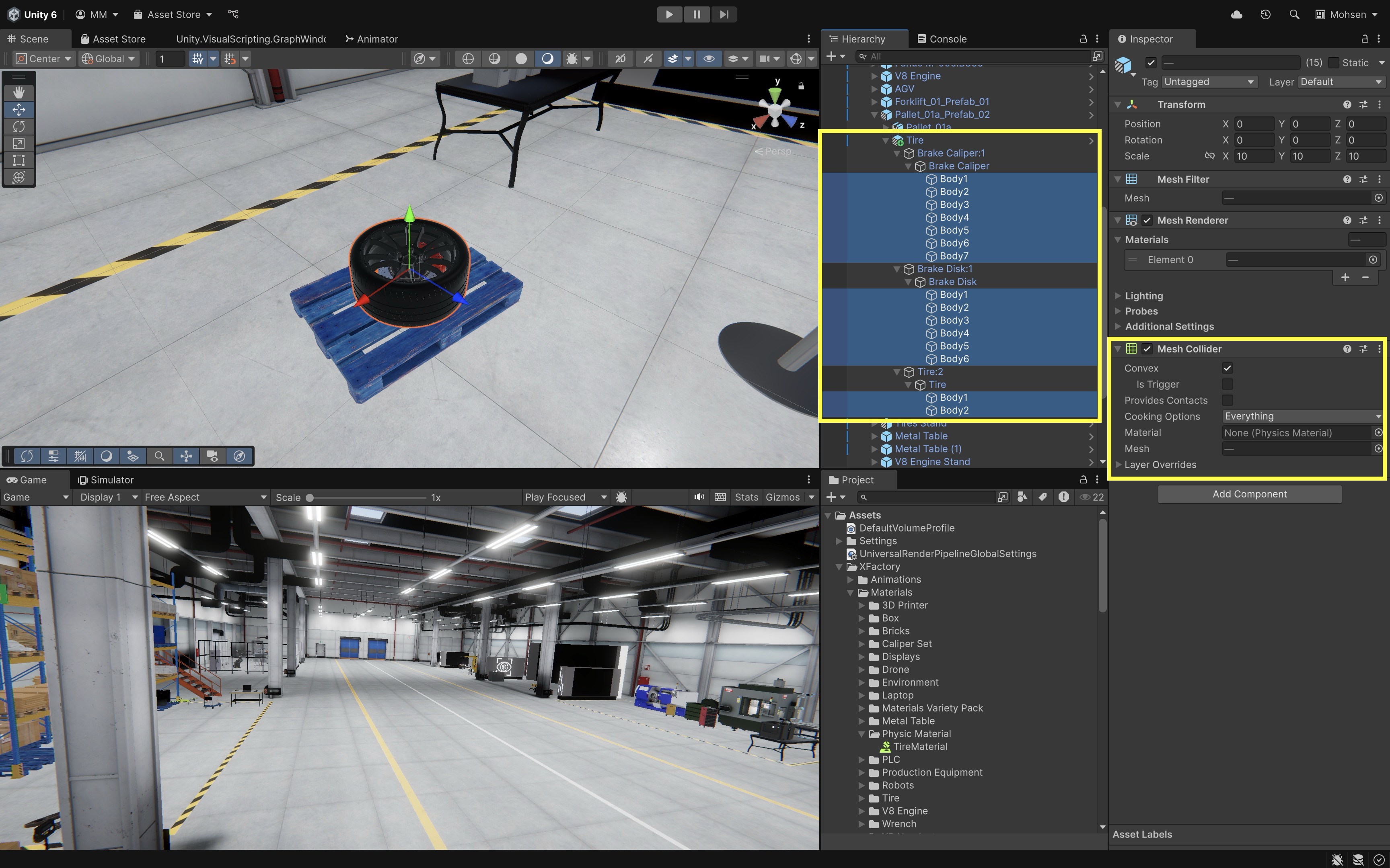
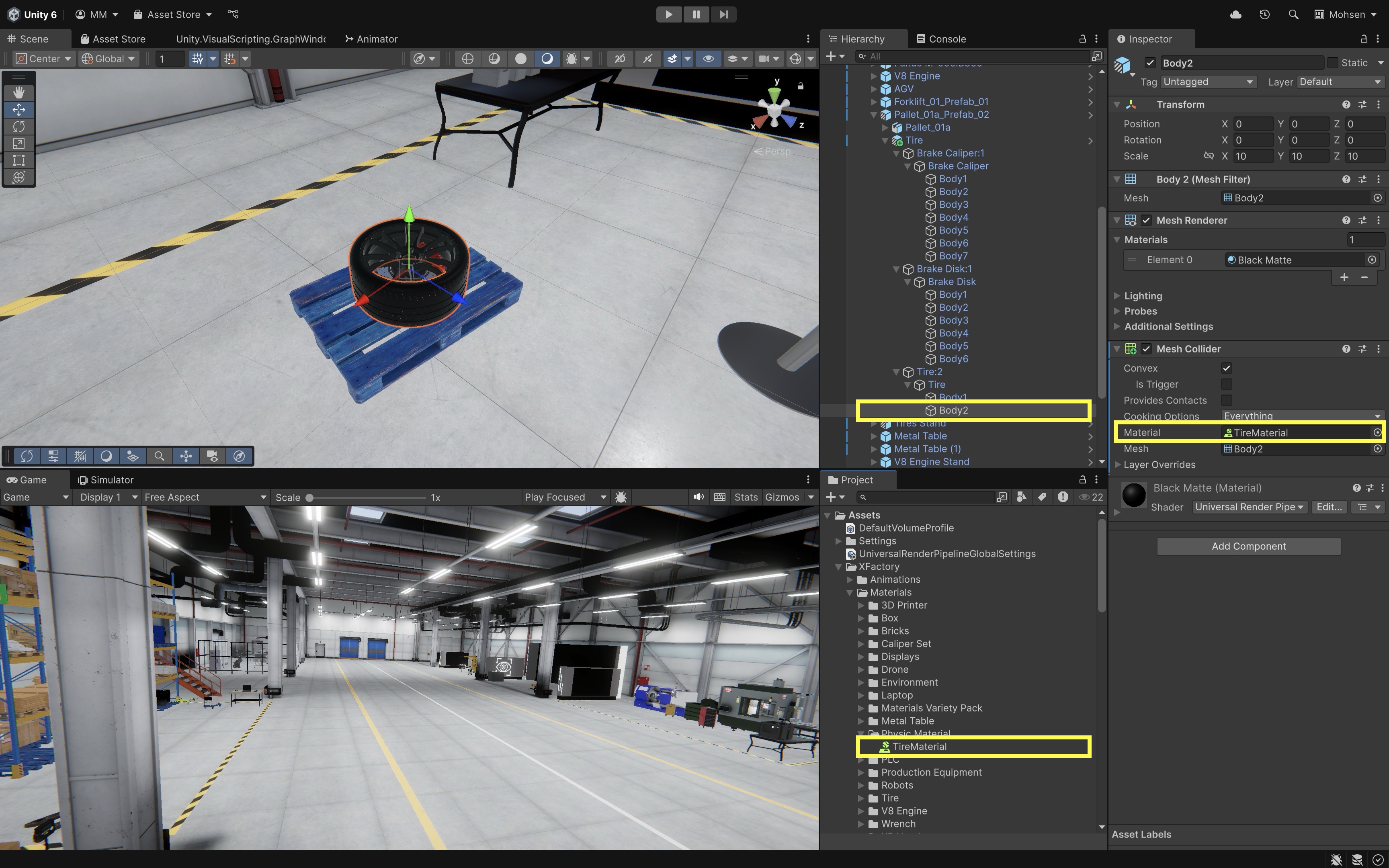
Colliderto allow the tire to interact with surfaces. Use either aCapsule Collider(simpler and efficient) or aMesh Collider(for detailed shape - enableConvex). Make sure to assign theMesh Colliderto the child GameObjects that contain both theMesh FilterandMesh Renderer, as the collider requires a mesh to function properly.
- In the
- Create a
Physics Material:- In the
Projectwindow, navigate toAssets > Materials > Physics Material(or a similar path to ensure proper organization). - Right-click and choose
Create > Physics Materialor use the equivalent Physics Material option shown in your Unity 6.3 Create menu, then name itTireMaterial. - In the
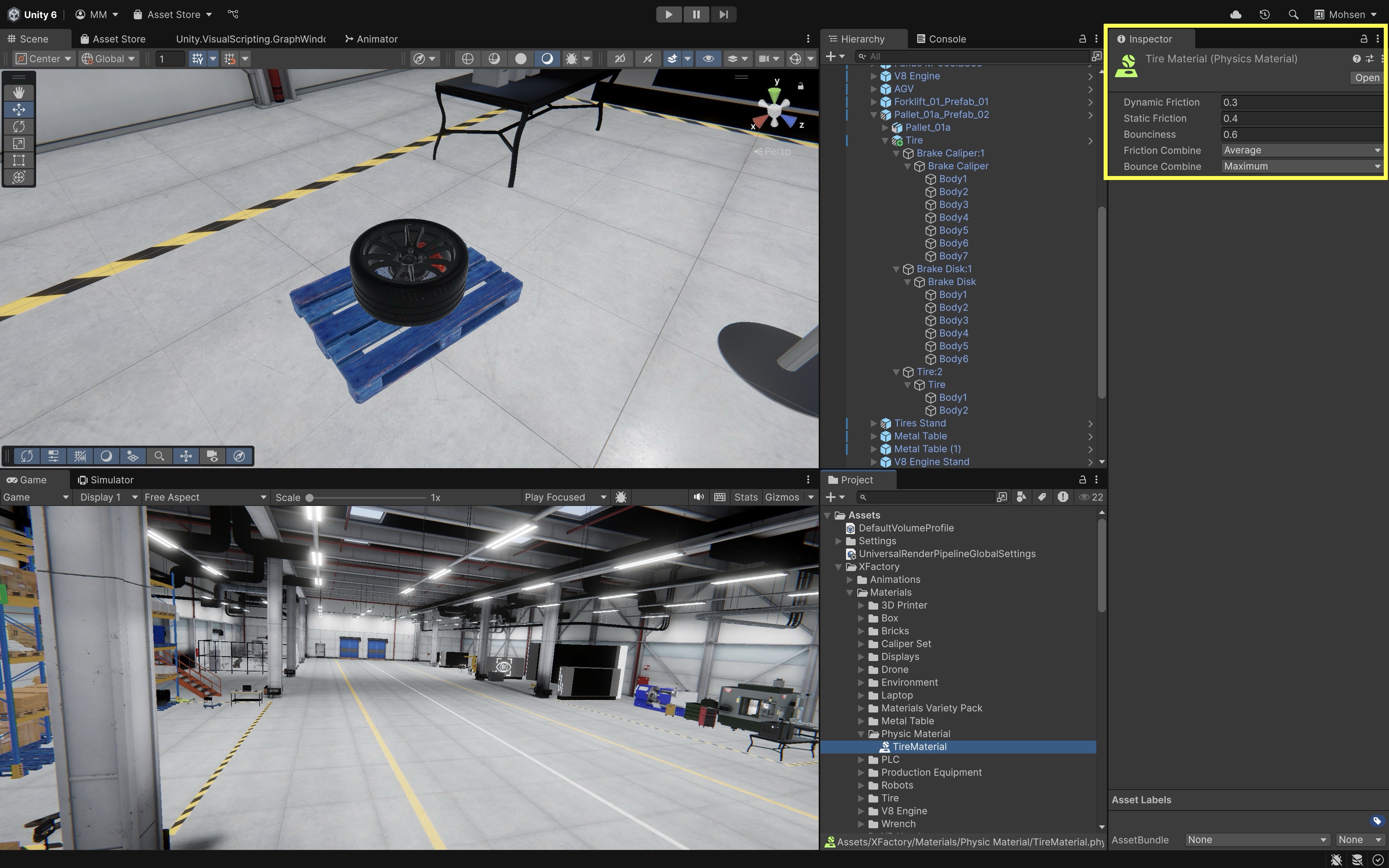
Inspector, configure the material to define how the tire behaves when rolling and bouncing. Dynamic Friction = 0.3simulates rolling resistance and contact with the floor.Static Friction = 0.4requires some force to get the tire moving from rest.Bounciness = 0.6allows moderate bounce upon impact.Bounce Combine = Maximumprioritizes the higher bounciness value during collisions.
- In the
- Assign
Physics Materialto the Tire:- Select the tire in the scene.
- In the
Collidercomponent (e.g.,Mesh Collider) of the child GameObject with rubbery material, assign theTireMaterialto theMaterialfield by dragging it from theProjectwindow. - This controls how the tire interacts with the floor and other surfaces as it moves and collides.
- Ensure Floor, Walls, and Pallet Have Colliders:
- Select the shop floor object (
Floor_Merged) and add aBox Colliderso it can register collisions. - Repeat the same for the walls (
Walls_Merged). - The wooden pallet should also have a
Box Colliderto support realistic contact when the tire rolls off its edge.
- Select the shop floor object (
- Set Up the Tire for Movement:
- Use the
Move ToolandRotate Toolto position the tire above and near the edge of the pallet. - Tilt it slightly or raise one side so that it naturally begins to roll off the pallet when gravity is applied at runtime.
- Use the
- Run the Simulation:
- Press
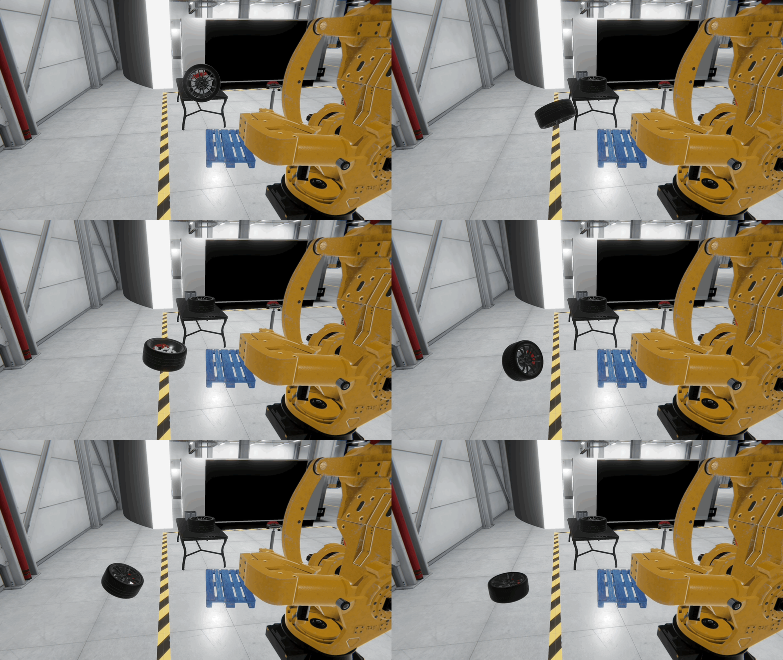
Playto start the scene. - Watch the tire roll off the pallet, bounce on the floor, and gradually come to rest based on the defined mass, damping, bounciness, and friction values.
- Try switching between a Box Collider and a Mesh Collider on the tire to observe how collider shape influences accuracy and realism.
- You can watch the rolling motion in a linked Meta Quest headset for a quick sense of scale and physics.
- Press
Joints
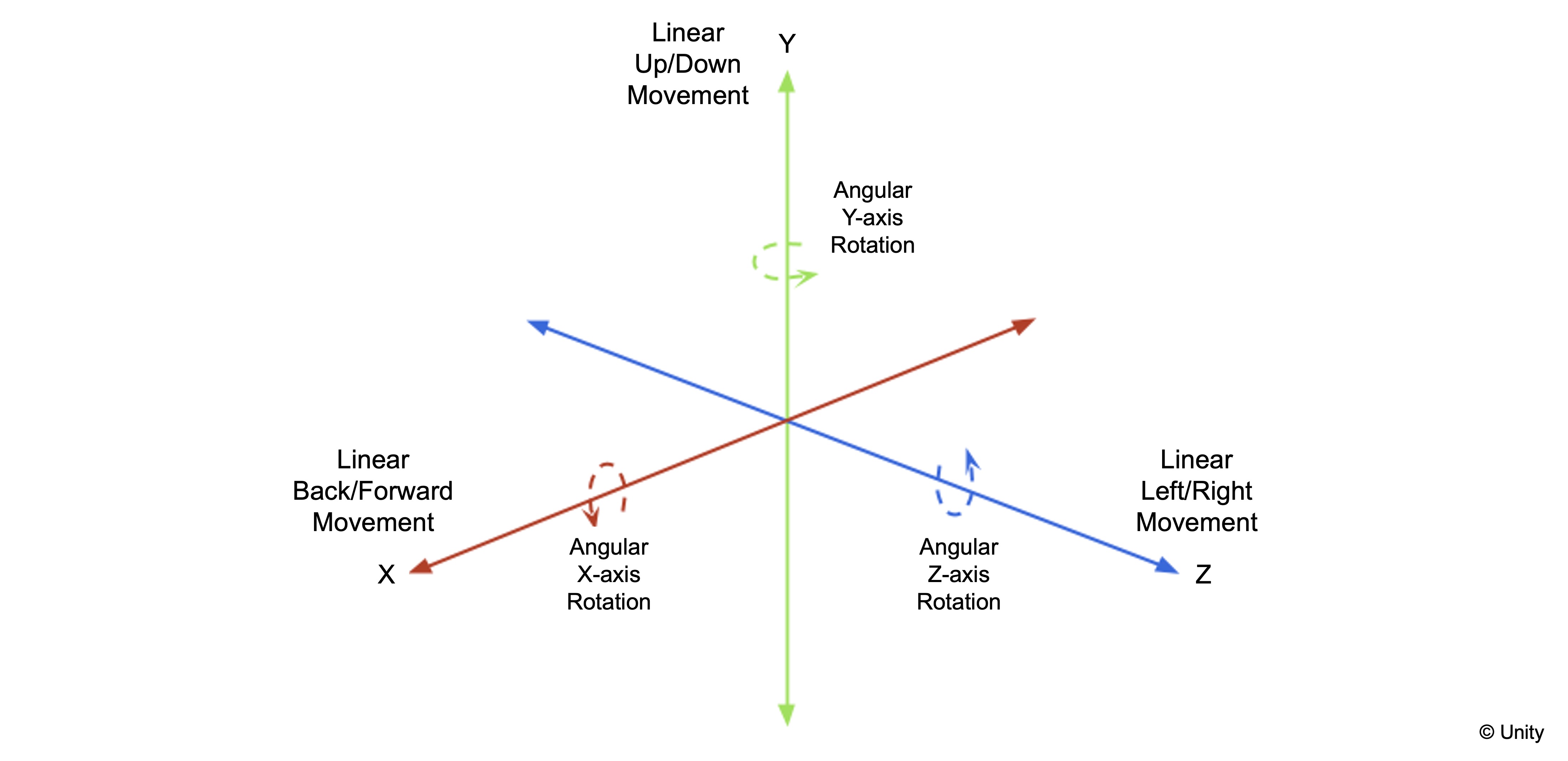
Joints connect Rigidbody objects or connect a Rigidbody to a fixed point in the world, allowing Unity to simulate mechanical constraints, linkages, and articulated mechanisms such as doors, levers, grippers, and simple machine parts. Standard joints are useful for interactive physical behavior, while ArticulationBody is more appropriate for advanced robotics-style joint chains.
Types of Joints
Hinge Joint: Allows rotation around one axis, making it suitable for simulating mechanical pivots and simple articulated motion. This can be used for simulating robotic gripper movements or the swinging door of a storage cabinet in the logistics area.Fixed Joint: Locks two objects together rigidly so they move as one while still reacting to external forces and collisions. This is ideal for attaching tools to the robot on the mobile base in the assembly station.Spring Joint: Connects objects with spring-like behavior, allowing for controlled elasticity and damping during movement. This can be used to simulate shock-absorbing mounts for equipment or cable tensioning in the production station.Configurable Joint: Provides detailed control over movement and rotation constraints along all axes, supporting complex mechanical interactions. This is useful for advanced simulation of a 6-DOF robotic arm in the tech station or fine-tuning a robotic gripper mechanism in the assembly area.
Simulating a Joint
Let’s simulate the opening and closing motion of a door using a hinged door. This example demonstrates how to configure a Hinge Joint to replicate realistic door articulation, commonly used in physical environments where interactive mechanics are needed. This setup is suitable for building realistic simulations for access control, safety barriers, or interactive environments.
- Use Existing Door in the Scene:
- In the
Hierarchy, locate a hinged door GameObject in the XFactory scene (e.g.,Door_01or another appropriate door object). - Ensure the door is a separate GameObject, parented under a static door frame or wall (e.g.,
Door_01_Prefab_01), which serves as the stable base.
- In the
- Add
RigidbodyandHinge Jointto the Door:- Select the door GameObject.
- Add a
Rigidbodycomponent if it does not already have one. - Add a
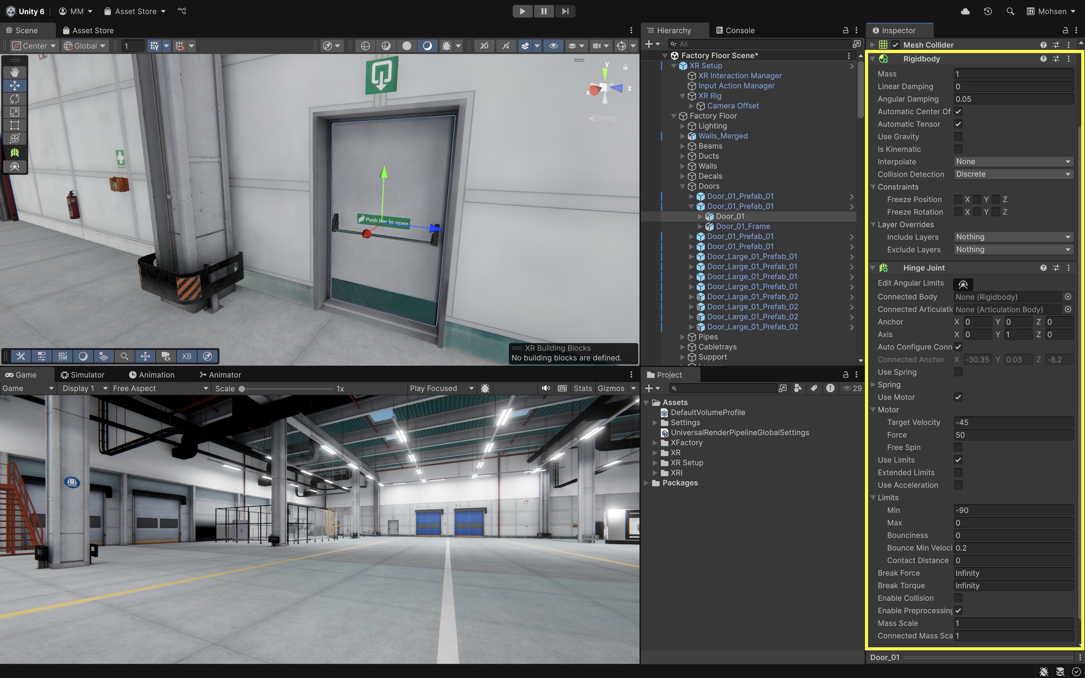
Hinge Jointcomponent usingInspector > Add Component > Hinge Joint. - In the
Rigidbodycomponent, disableUse Gravityso the door is not pulled downward. - Leave
Is Kinematicdisabled if you want the door to respond to joint motor forces and physical interaction.
- Configure
Hinge JointSettings in theInspector:- Leave the
Connected Bodyfield empty if you want the hinge to connect to the world rather than another Rigidbody. If the door should be physically connected to a moving frame or mechanism, assign that object’s Rigidbody toConnected Body. - Set the
Anchorto the hinge side of the door—typically near the edge where the door rotates. Use Scene view Gizmos to adjust and preview the rotation axis. - Set the
Axisto define the direction of rotation. For most doors, use(0, 1, 0)if the door rotates around the Y-axis.
- Leave the
- Apply Joint
Limits:- Enable
Use Limits. - Expand the
Limitssection of theHinge Joint. - Set
Min = -90andMax = 0(so the door opens towards outside). - This constrains the door to swing open up to 90°, simulating realistic physical constraints of a hinged door.
- Enable
- Enable Motor (Optional):
- Enable
Use Motor. - Set
Target Velocity = -45(degrees per second), so the door opens counterclockwise. - Set
Force = 50to define how strongly the motor pushes. - Set
Free Spin = falseto allow precise controlled rotation.
- Enable
- Run the Scene:
- Press
Playto test the simulation. - The door should rotate naturally within the defined limits.
- If
Use Motoris enabled, the door will automatically begin swinging open—simulating an automated door mechanism. - Make sure the moving door object is not marked as static. Static objects are intended for objects that do not move.
- A Quest Link–connected headset lets you preview the door swing in VR from the Editor—hands-on interaction comes later in Module D.
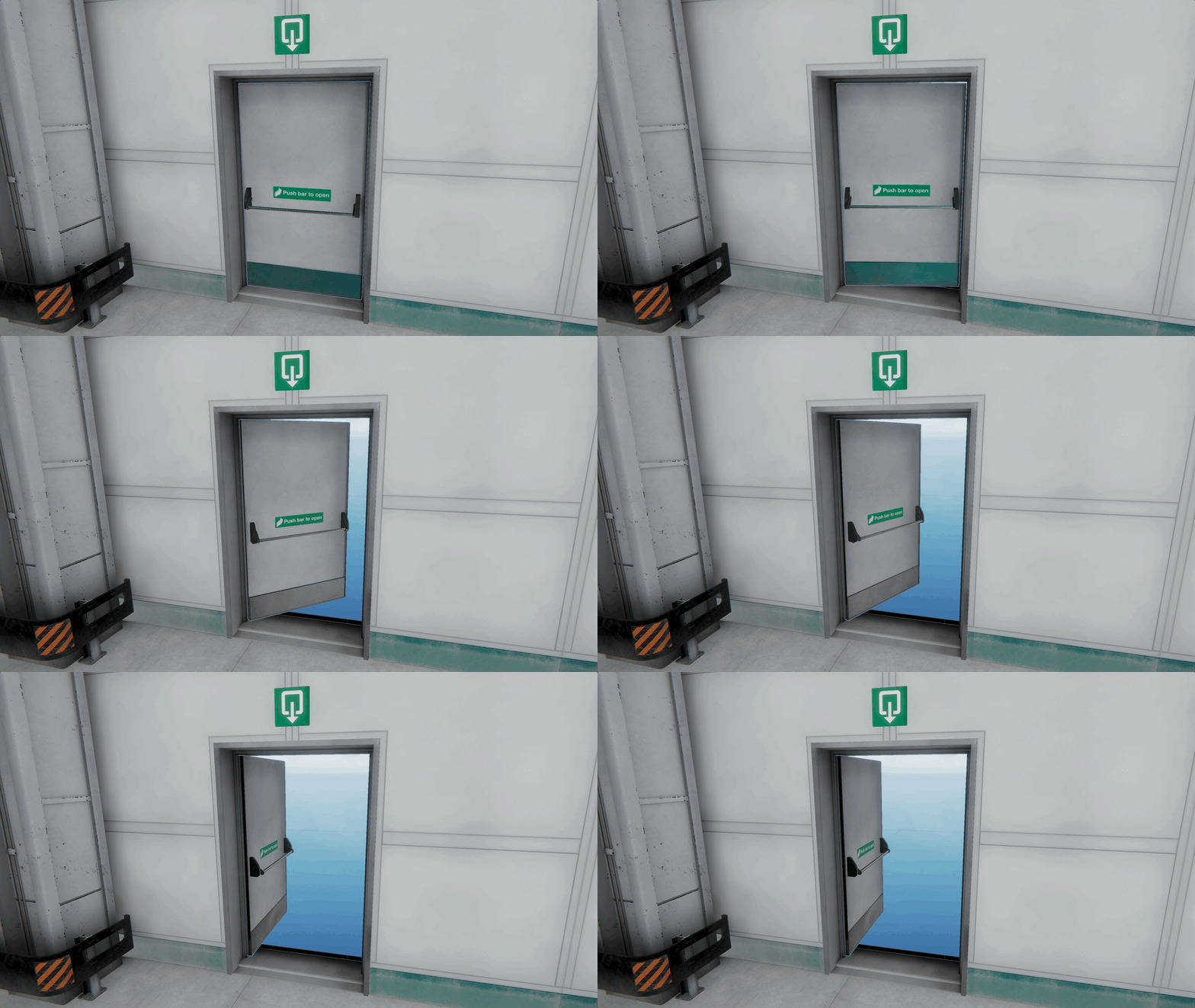
Joints are important for simulating real-time, physics-based interactions, allowing objects like doors to respond dynamically to forces, collisions, and user input. Unlike animations—which play predefined motions—joints enable interactive, physics-based behavior that’s essential for realistic simulations.
- Press
Animating GameObjects

Unity’s animation system is a powerful tool for adding movement and dynamic behavior to objects within a scene. Animations enhance interactive experiences by making characters, environments, and UI elements feel more engaging and lifelike. While complex character animations (such as facial expressions or fluid movements) are typically created in external digital content creation software like Maya, 3ds Max, and Blender, Unity also provides built-in tools for creating scene-based animations (such as moving platforms, opening doors, robotic arm movement, or UI transitions). Unity has both an older Animation component and the newer Mecanim/Animator workflow. This course uses the Animator component, Animation Clips, and Animator Controllers for most runtime animation because they support state machines, transitions, parameters, and imported clips.
In XFactory, animations can be used to illustrate a forklift loading a box onto a rack, a robotic arm assembling engine components, or CNC machinery operating as part of a production process. These animations not only improve realism but also support educational and operational objectives in engineering simulations.
Core Concepts
- Animation Clips: An Animation Clip is a timeline of movement and property changes applied to GameObjects. Each clip consists of keyframes, which record specific attributes (like position, rotation, scale, or material properties) at precise moments. Unity then interpolates the changes between keyframes to create smooth, continuous motion. In XFactory, you can use an animation clip to show a drone lifting off from the logistics station and scanning QR codes on boxes.
- Animator Controller: An Animator Controller manages different animation clips and defines how an object transitions between them. It provides logic to switch between animations using conditions such as user input, machine states, or scripted triggers. A robotic arm in the assembly station might switch between “Idle”, “Pick Part”, and “Assemble Part” states depending on a simulation event.
- Animation States and Transitions: These are part of the Animator Controller. Each state represents a single animation (e.g., “Idle”, “Moving”, “Operating”), and transitions define when and how an object shifts from one state to another. Conditions like a sensor detecting an object or a timer completing can trigger transitions. The mobile robot in XFactory might transition from “Waiting” to “Moving to Assembly Station” when the operator triggers a command.
- Rigging and Skeletal Animation: For complex models like humanoid figures, quadrupeds, or articulated robots, a rig is used. A rig consists of a skeleton or hierarchy of bones that drives mesh deformation. Skeletal animation manipulates these bones to animate the model. The quadruped robot in the tech station requires a generic rig to animate each leg’s movement while walking across the lab floor. Unity also provides optional animation rigging tools for advanced constraints and procedural adjustments.
- Keyframes: Keyframes mark when specific properties of a GameObject change. Unity’s Animation Window allows users to define keyframes for objects manually. Between keyframes, Unity calculates the in-between frames to ensure smooth transitions. Keyframes can animate the movement of a welding robot arm in the welding station as it joins two car parts.
- Blend Trees: A Blend Tree blends between multiple animations based on input parameters (e.g., speed, direction). This is useful for continuous movement where smooth transitions are necessary. A mobile robot in the assembly area could use a Blend Tree to blend between turning, accelerating, and reversing animations.
- Animation Events: These allow you to trigger code or actions at a specific frame of an animation. Useful for syncing animations with sound, effects, or gameplay logic. During a robotic machine tending animation, an event can be triggered when the part hits the machine table or tending table to play a thud sound and activate a vibration effect.
Animation Methods
-
Using the Animation Window (In-Editor Animation): Unity’s Animation Window enables visual keyframe-based animation directly within the editor. Ideal for animating simple or mechanical objects that require straightforward motion. In XFactory, you can animate the opening and closing of the CNC machine’s door or a forklift belt moving pallets from one station to another.
-
Animator Controller Setup: The Animator Controller manages logic-driven animations. It enables objects to change animations dynamically based on simulation or user-defined conditions. In XFactory, the CNC machine in the production station starts its “Processing” animation when the simulation triggers a start command.
-
Importing Animations from External Software: For complex motion and high-quality rigs, animations are often created in tools like Maya, 3ds Max, or Blender, then exported as
.FBXfiles and imported into Unity. These can be configured for humanoid or generic rigs in Unity’s import settings. In XFactory, you can import detailed quadruped movement sequences created in Blender to use in the exhibition station simulation.
In-Editor Animation
Let’s create an animation in Unity, focusing on a flying drone in a logistics station that moves between racks, hovers to scan packages, and lands/takes off. For a drone, this includes flying between racks (Position), hovering to scan (Scale or light pulse), landing / Take-off (Position, Scale), and scanning pulse effect (Material color, Emission, or Scale). This kind of animation enhances realism for warehouse simulations, drone fleet management systems, or XR-based operational training.
Creating an Animation Clip
An Animation Clip is a Unity asset that stores timed transformations (position, rotation, scale, etc.). Let’s start by creating a simple hover and scan animation for the drone:
- Open your XFactory Unity scene and navigate to the logistics station.
- In the
Hierarchy, select the drone GameObject (Drone) or the scanning component (Eye). - Open the
Animationwindow (Window > Animation > Animation) and clickCreate. - Name the clip
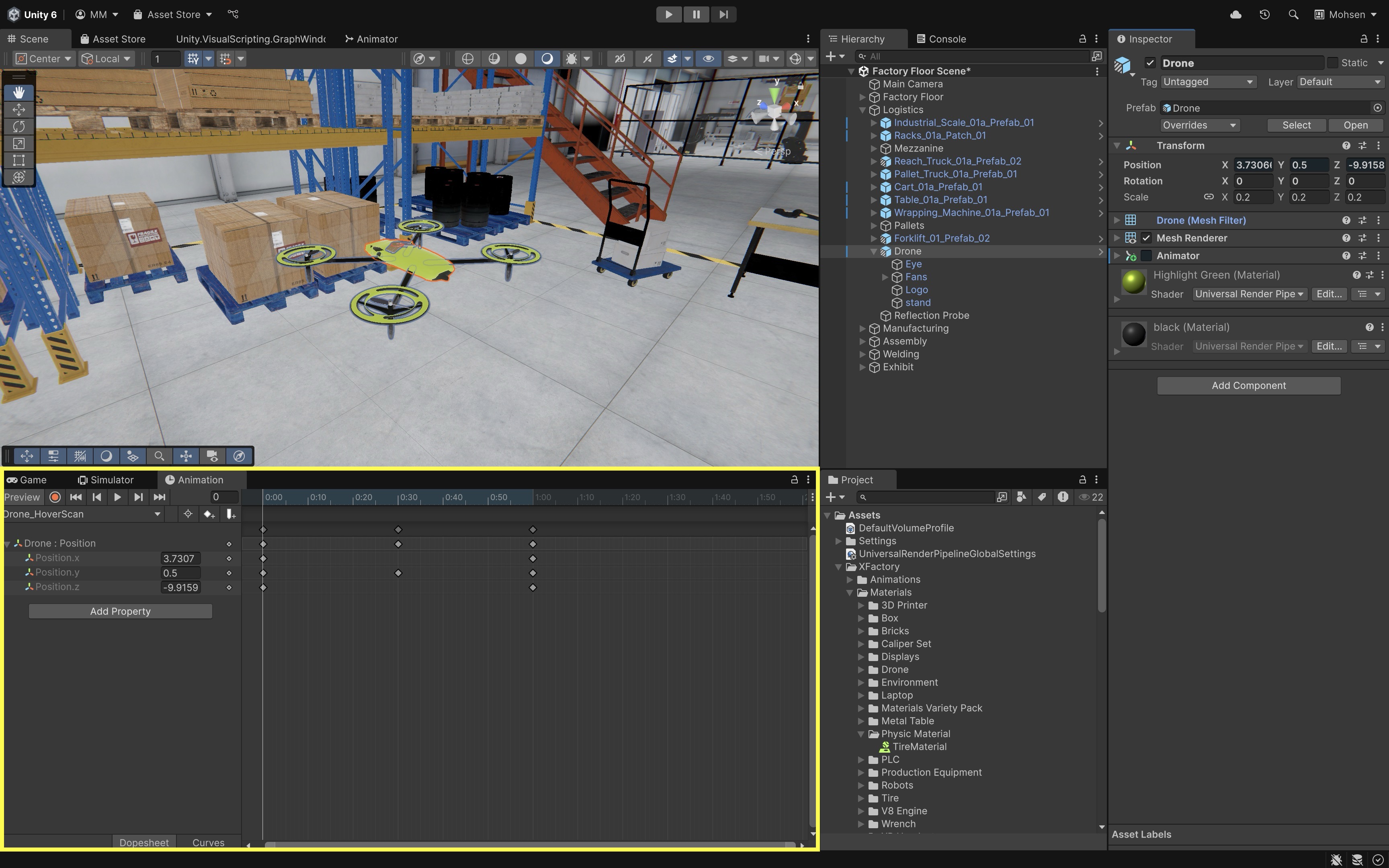
Drone_HoverScanand save it in anAnimationsfolder. - Select the drone GameObject (
Drone) in theHierarchy.- Add a
Transform > Positionproperty to create a hovering effect. - Start with
Y = 0.50, move toY = 0.55at 0.5s (viaAdd keyframe), and return toY = 0.50at 1s for a gentle hover loop.
- Add a
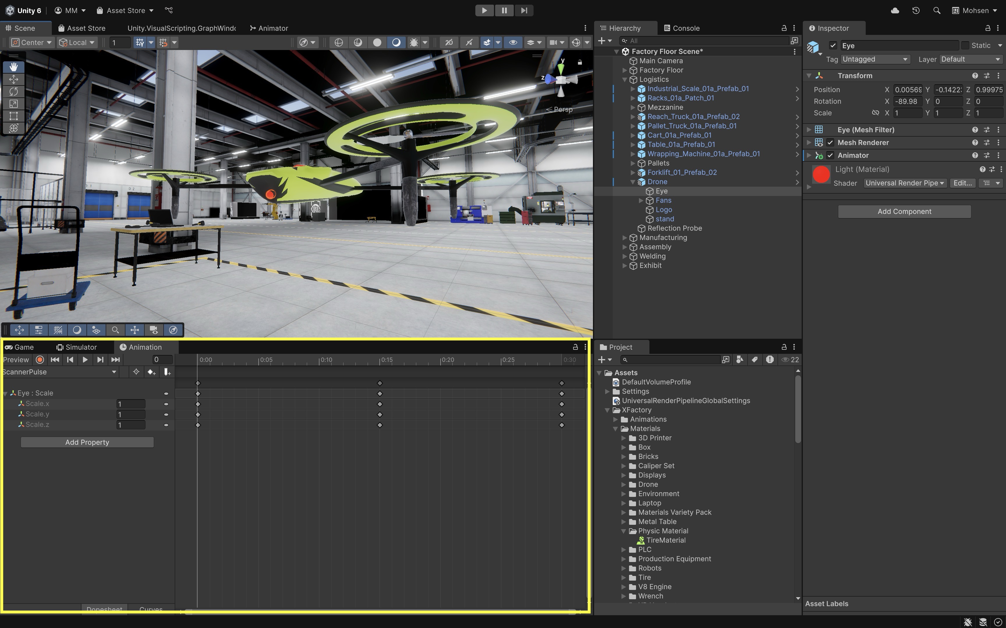
- Select the scanning component (
Eye).- In the
Inspector, clickAdd Component > Animatorif it doesn’t already have one. - Create a new animation for this component.
- Add
Transform > Scaleto simulate a pulsing scan light. - Set initial scale to
(1, 1, 1), increase to(1.2, 1.2, 1.2)at 0.25s, and back to(1, 1, 1)at 0.5s.
- In the
-
Press the
Playbutton in the Unity Editor. Observe the drone gently bobbing up and down while the scanner component pulses in scale, simulating a live hover-and-scan behavior. The hover animation can also be viewed in a Meta Quest headset through Quest Link during Play Mode.If the animation doesn’t play, make sure the object has an
Animatorcomponent and that your clip is assigned to it. You can also loop the animation by enablingLoop Timein theAnimationclip’s settings (Inspector > Loop Time).
Smoothing an Animation
To make the drone’s hover animation feel more realistic, you can smooth its vertical motion using Unity’s Curves editor, which controls the speed and acceleration of animated values.
- Open the
Animationwindow and select yourDrone_HoverScanclip. - Switch to
Curvesmode using theCurvesicon in the bottom-left of the timeline. - Select the
Transform.Position.ycurve. - Right-click on keyframes and choose
AutoorEase In Outto apply natural acceleration and deceleration. -
Adjust curve handles to fine-tune the timing and smoothness of the rise and fall.
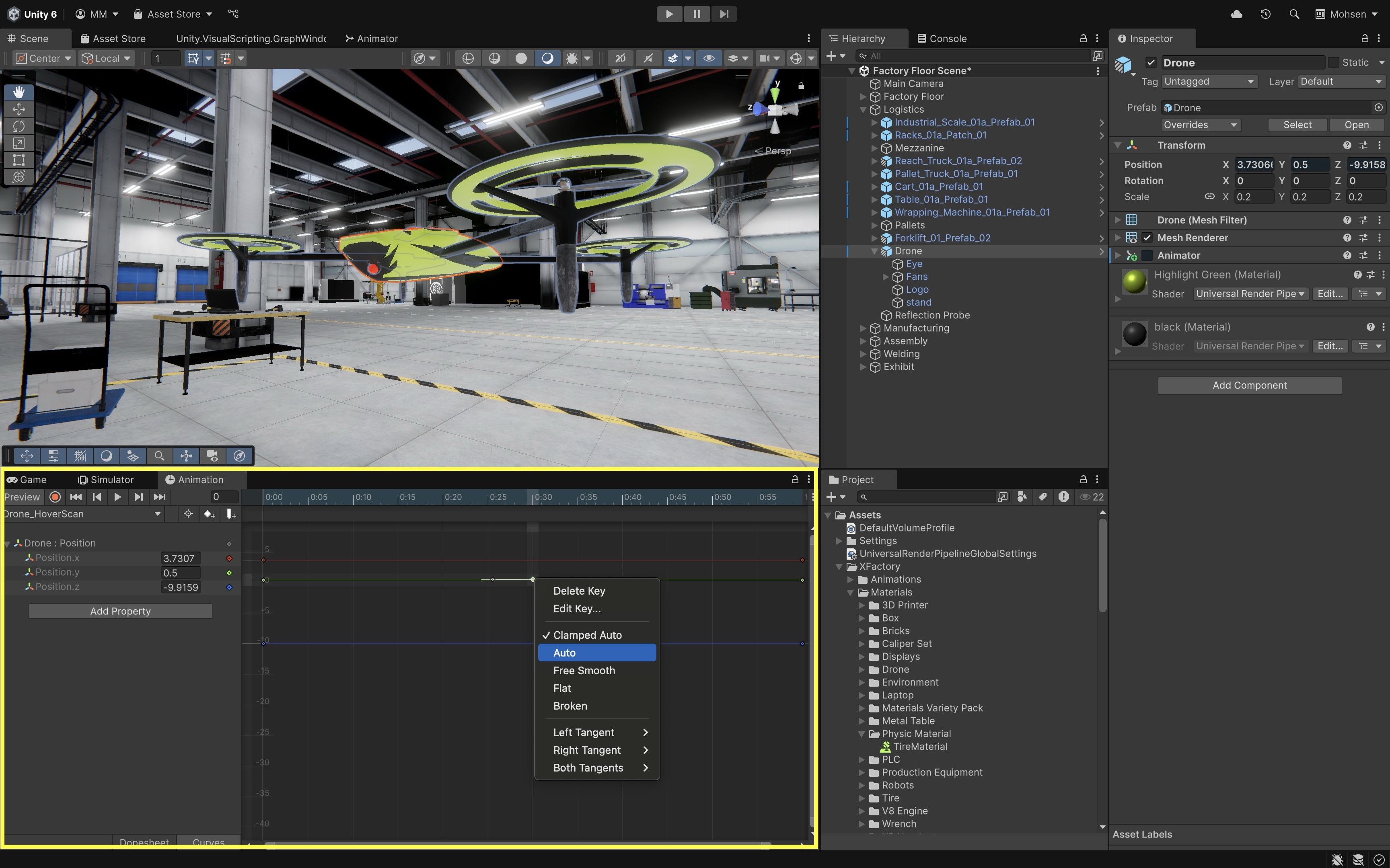
This gives the drone a more natural hover effect, mimicking how drones subtly slow down before changing vertical direction—ideal for training simulations or drone fleet visualizations.
Recording an Animation
For this exercise, duplicate the scanner-eye material before animating emission if the same material is shared by other objects. Otherwise, changing or animating the material may affect every object using that shared material. Now, let’s animate the emission color of the drone’s scanner eye to pulse from yellow → red → yellow, simulating an active scanning state. In this example, we will use the recording method to add it manually.
- Select the material applied to the
EyeGameObject. In theInspector:- Ensure the shader is
URP/Litor another shader that supports emission. - Check the
Emissionbox to enable emission properties. - Set the initial
Emission Colorto a visible value like yellow.
Emission makes the material appear bright. To create a visible glow around the object, the scene may also need bloom or post-processing, which is covered in the rendering session.
- Ensure the shader is
-
In the
Hierarchy, select theEyeGameObject. Open theScannerPulseclip. -
Click the record button (red circle) in the
Animationwindow. - In the
Inspector, under theMaterialsection:- Click the color box next to
Emission Colorand change it to red. - Move the playhead to
0.1s, then change the color back to yellow. - Move the playhead to
0.2s, and return to red again. - Click record again to stop recording.
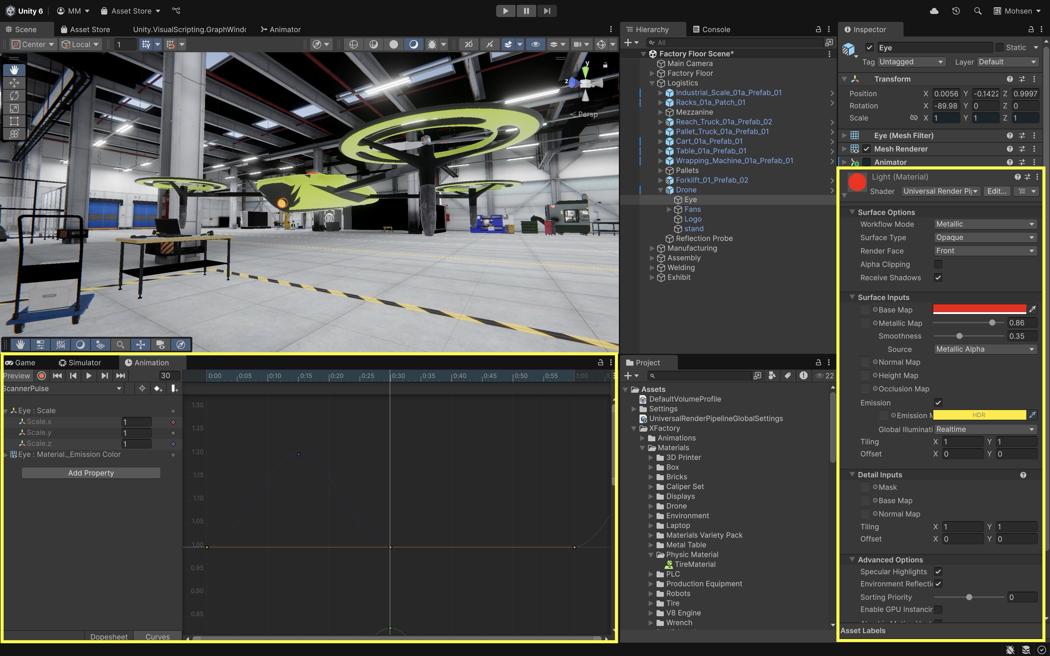
- Click the color box next to
-
Select the
ScannerPulseanimation clip in theProjectwindow. In theInspector, checkLoop Timeso the pulse continues during runtime. -
When you press
Play, the drone’s eye will now emit a glowing pulse that cycles between red and yellow—simulating an active scanning state. With Quest Link active, you can see the pulsing material in your linked Meta Quest headset too.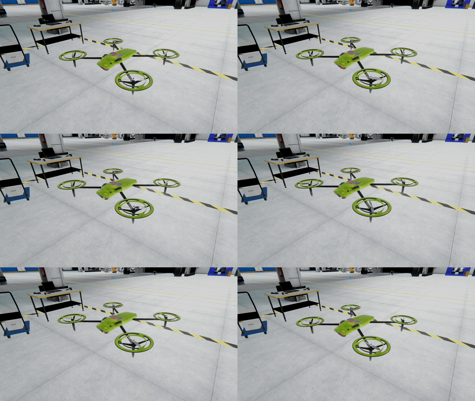
Animator Controller
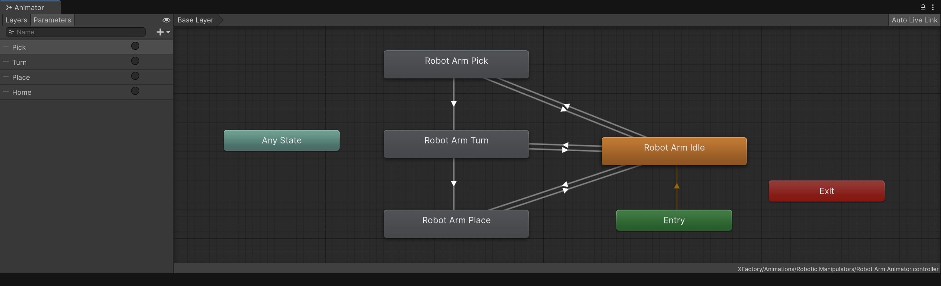
The Animator component controls animation playback on a GameObject using an Animator Controller. The controller defines animation states, transitions, parameters, and optional layers. In engineering environments like XFactory, Animator Controllers can manage robots, drones, machinery, doors, indicators, or UI behaviors that switch between discrete states such as idle, scanning, moving, and returning.
Core Concepts
- Animator Component: Attached to a GameObject, it links to an
Animator Controllerthat drives the animation logic. - Animator Controller: The control hub for animations, defining states, transitions, and parameters.
- State Machine: Organizes animation states (e.g., Idle, Walking) and controls how they transition.
- Parameters: Input values that trigger transitions:
Bool: Toggle behavior (IsEngaged)Int: Mode selector (OperationMode)Float: Sensor values (MotorLoad)Trigger: One-time actions (StartWalking,ReturnToBase)
For the quadruped robot in XFactory, typical states may include
Idle → Scanning → Walking → Returning.
Animate with the Animator
Let’s use Unity’s Animator to control simple drone states—hovering and moving—using basic transitions. This is a simpler setup than animating limb joints and is ideal for creating modular drone behavior like patrolling, scanning, or flying between zones.
- Set Up the Scene:
- Open your Unity scene with the drone in the logistics station.
- Select the root GameObject (
Drone). - In the
Inspector, add anAnimatorcomponent if it is not already present.
- Set Up the Animator Controller:
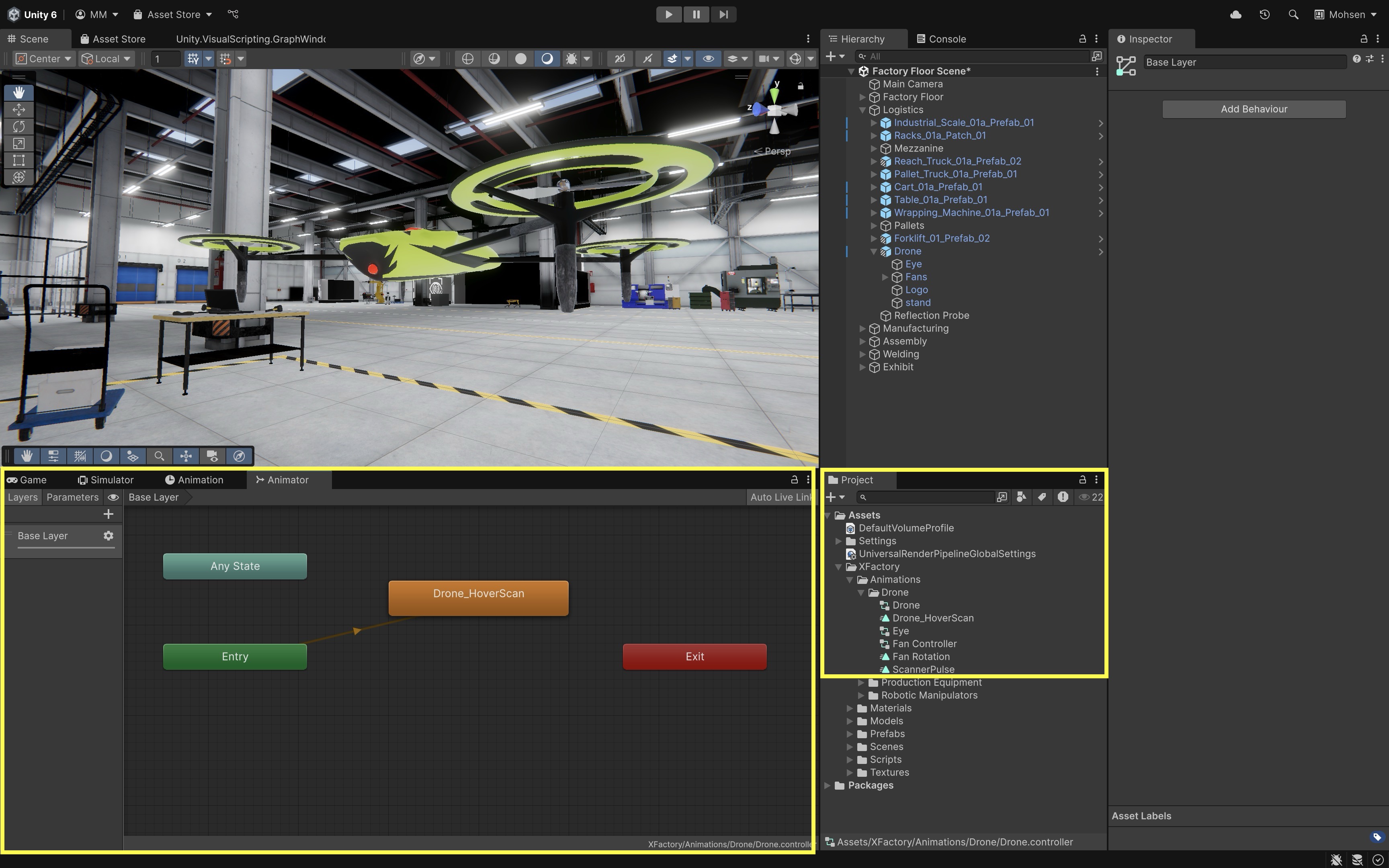
- In the
Projectwindow, locate the auto-createdAnimator Controller(e.g.,Drone). - Double-click to open the
Animatorwindow. - Drag your
Drone_HoverScananimation into the grid—this becomes a new state. - Make
Drone_HoverScanthe default state if it is not already connected fromEntry. You can usually do this by right-clicking the state and choosingSet as Layer Default State.
- In the
- Create a Simple Patrol Movement Animation:
- With
Dronestill selected, create a new clip namedDrone_MoveForward. - Animate
Transform.Position.zto simulate basic forward motion. Setz = -10in Frame 0 andz = -8.5in Frame 2s. - Save and stop recording.
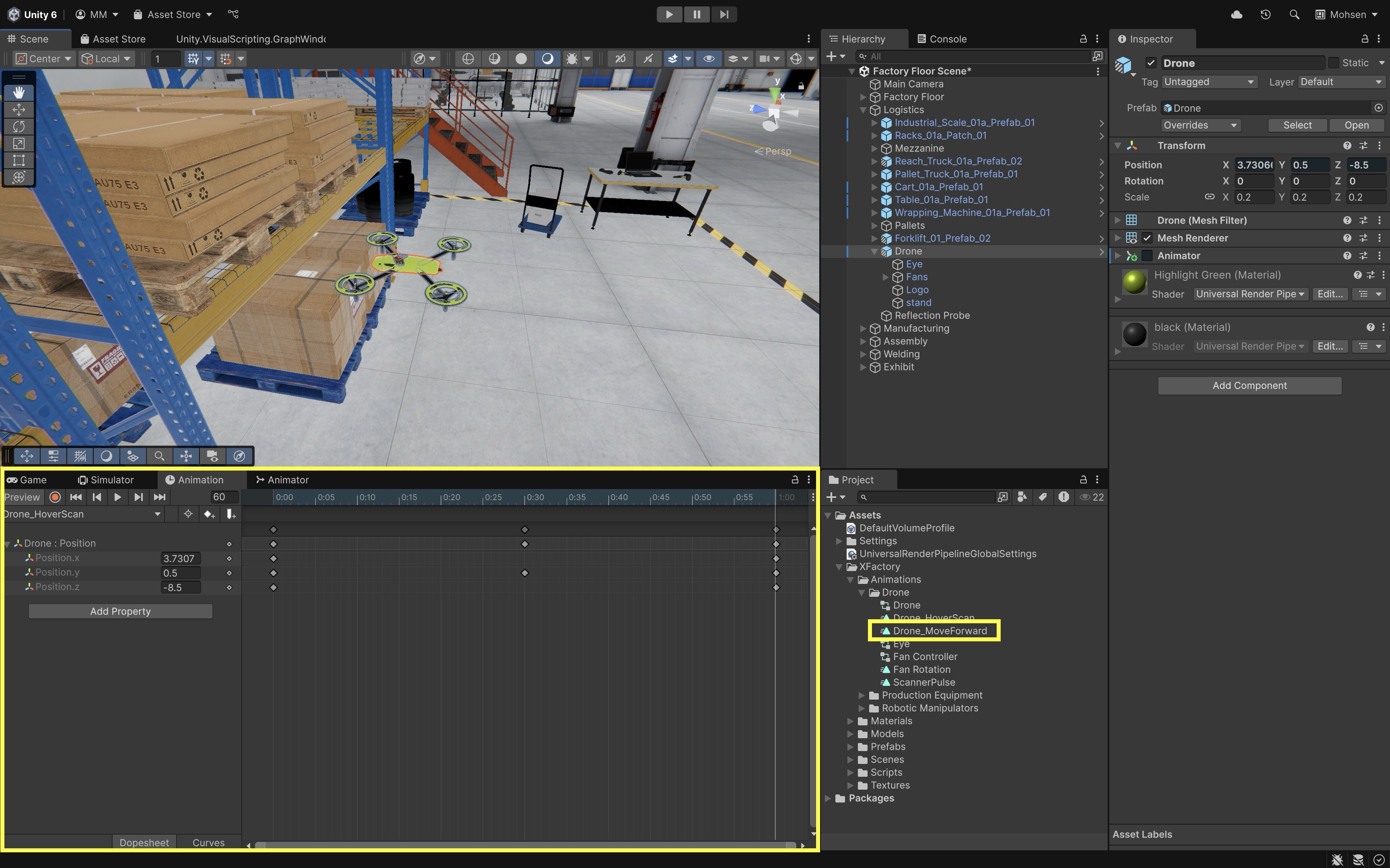
- With
- Build the State Machine:
- Switch to the
Animatorwindow. - Drag
Drone_MoveForwardinto the grid. - Create a transition from
Drone_HoverScan → Drone_MoveForward. - Add a new
Triggerparameter namedStartFlying. - Set this as the transition condition.
- Create a return transition from
Drone_MoveForward → Drone_HoverScan. - Add another
TriggercalledReturnToHover. - Uncheck
Has Exit Timeand reduceTransition Duration(e.g.,0.1) for instant state changes.
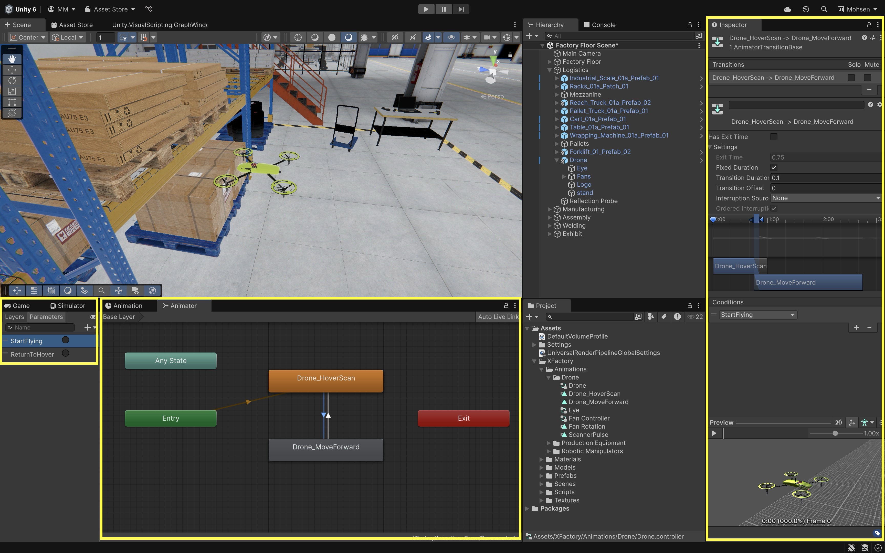
If the transition does not happen immediately when you press a trigger, check
Has Exit Time, transition duration, and transition conditions in the Inspector. - Switch to the
- Test the Setup:
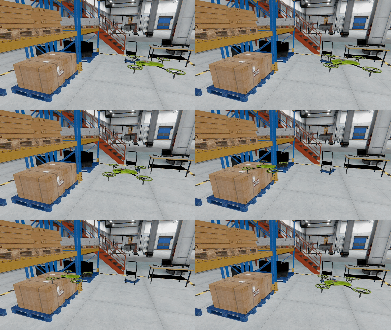
- Enter
Playmode. - Open the
Animatorwindow while the scene is running. - Manually click the
StartFlyingtrigger. The drone should fly forward. - Click
ReturnToHover. The drone returns to hover mode. - Trigger the states in Play Mode and you can follow the drone motion in a Quest Link–connected headset as a visual preview.
- Enter
- Optional State Ideas:
ScanPulse: Animate emission color for the eye using material properties.Land: Animate the Y-position to descend onto a platform.Idle: No animation—used for drones in standby.TakeOff: One-time lift-off motion before switching to hover.
This Animator-based setup is perfect for simple autonomous drone behavior, simulation training, or AI-driven animation without scripting complex logic.
Importing Animations
Detailed animations, such as walk or patrol cycles for quadruped robots, are often created in tools like Blender or Maya. Animations are commonly exported as .FBX files and imported into Unity. Ready-made animations can also come from sources such as Mixamo, TurboSquid, Sketchfab, or ActorCore, but licensing, rig compatibility, and retargeting must be checked carefully. For robots and quadrupeds, use Generic rigs unless you are intentionally working with a humanoid/biped skeleton. Now, let’s use an imported animation to animate the quadruped robot in XFactory:
- Import the Animation File:
- Download or export the animation as an
.FBXfile. - Drag it into your Unity project’s
Assets > Animations > Spotfolder. - Select the
.FBXfile in theProjectwindow. - In the
Inspector, switch to theRigtab. - Set
Animation TypetoGeneric. - In
Avatar Definition, chooseCreate From This Modelsince the FBX has its own skeleton. Set theRoot nodeto the appropriate root bone or root transform for the imported model. In the current Spot asset, this may beCINEMA_4D_EDITOR; if that node is not present, choose the actual root of the imported rig. - Click
Apply.
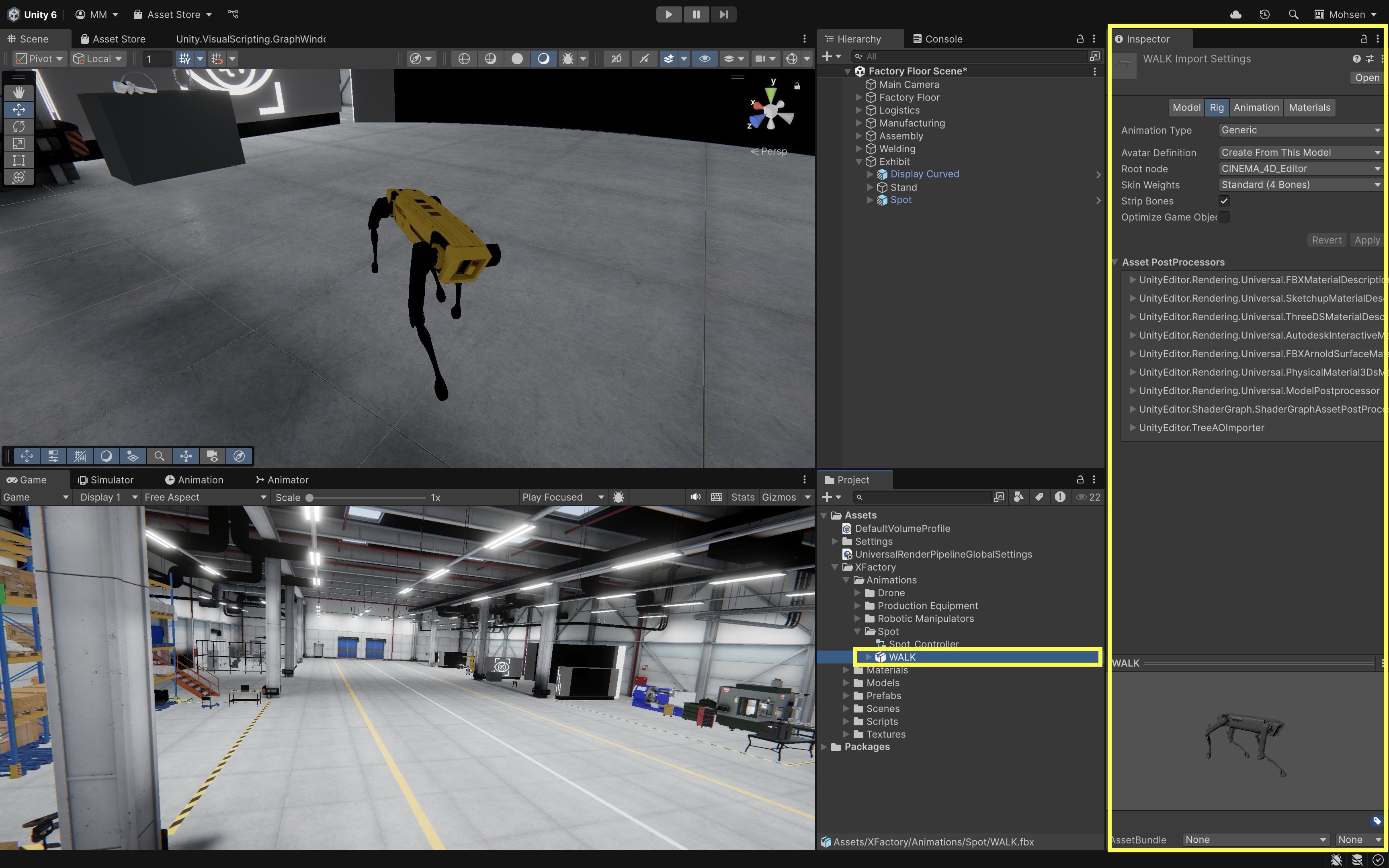
Genericanimation type is ideal for Spot’s robotic skeleton. AvoidHumanoidunless you’re retargeting from a biped source. - Download or export the animation as an
- Assign to the Model:
- In the
Projectwindow, create a newAnimator Controller, e.g.,Spot_Controller. - Drag your animation clips into the
Animatorwindow as states. - Select your
Spotmodel in theHierarchy. - In the
Inspector, assignSpot_Controllerto theAnimatorcomponent. - Set the
Avatarfield to the avatar generated from the imported rig, such asWALKAvatarif that is the avatar included with the current Spot asset.
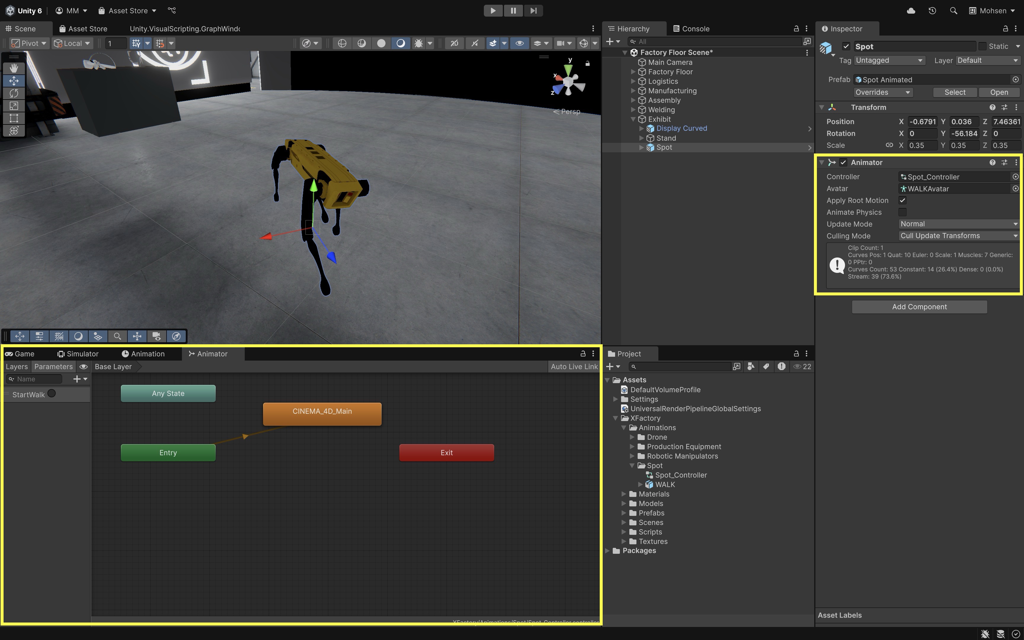
- In the
- Test the
Animator:- Open the
Animatorwindow and enterPlaymode. - Manually trigger the animation by adding
Triggerparameters likeStartWalk,StartScan, etc. or by setting up transitions based on those triggers in the Animator state machine. - Click each trigger to preview Spot’s motion live in-scene.
- Spot’s walk cycle can also be previewed in a linked Meta Quest headset before Module D introduces full VR interaction.
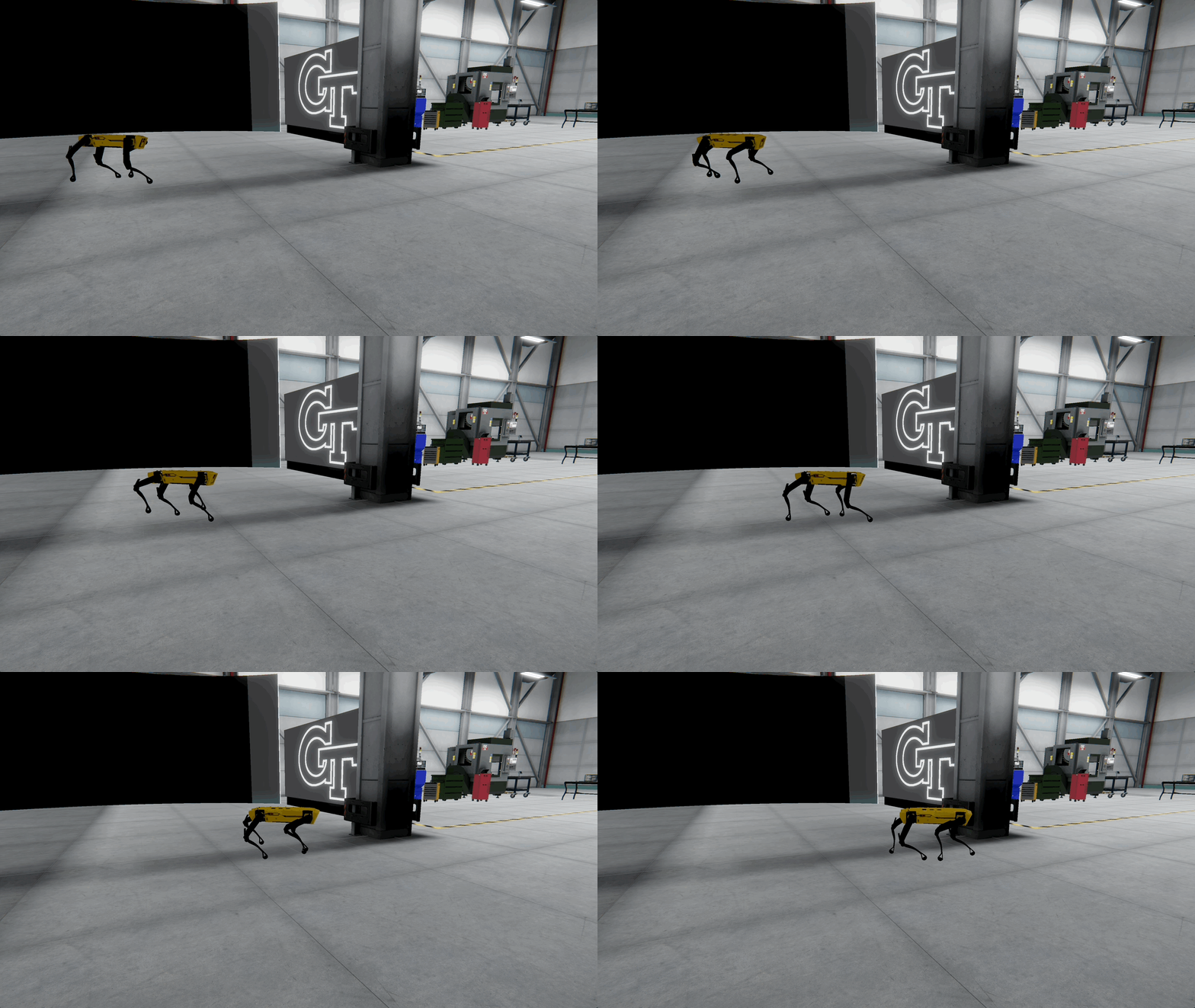
Physics vs. animation: Use physics when objects need to respond dynamically to forces, collisions, or user interaction. Use animation when motion should be authored, repeatable, and controllable. Many XR simulations combine both: animation for planned machine motion and physics for interactive objects, collisions, and user-driven manipulation.
- Open the
Key Takeaways
- Rigidbody, collider, and Physics Material settings define how objects move, collide, and respond to forces.
- Joints connect objects with physics-based mechanical relationships useful for doors, arms, and assemblies.
- Animation clips and Animator controllers bring motion to machines, tools, and environmental elements.
- Physics fidelity must be balanced against stability and performance—especially in interactive VR.
- Combining physics and animation supports believable machine behavior in engineering training simulations.