B2. Rendering
Learning Outcomes
- Identify and inspect meshes in Unity. In preparation, read about mesh fundamentals and Unity’s documentation, then open a scene and select several GameObjects to examine their
Mesh FilterandMesh Renderercomponents to see how meshes are organized.- Recognize and modify materials in Unity. Before class, locate a few GameObjects in the XFactory scene and check their materials in the
Inspector. Try dragging an existing material onto a GameObject to see how it alters its look.- Differentiate between Lit and Unlit shaders in Unity. As prep work, review URP shaders, focusing on Lit vs. Unlit types, then in Unity browse shader options in a material’s settings without making any changes yet.
- Apply textures to materials in Unity. Prior to class, find or download texture files (PNG or JPG), import them into your project’s
Texturesfolder, and drag one onto theBase Mapslot of a material to preview its effect in the scene.- Describe lighting types and their effects in Unity scenes. For preparation, read the overview of light types and real-time vs. baked lighting, then in Unity adjust existing lights in a sample scene to observe changes in intensity or type.
- Explain the basic concepts of rendering, pipelines, and methods in Unity and XR. Before class, review the introductory material on rendering, then explore Unity’s
Sceneview with the XFactory project to spot where materials, lighting, and post-processing appear.
What Is Rendering?

Rendering is the process of transforming 3D models, textures, lights, and effects into a 2D image that is displayed on the screen. It is the digital equivalent of photographing a real-world scene using a virtual camera. In XFactory, rendering enables high-fidelity, frame-by-frame visualization of the factory’s interior, exterior, and equipment. In XR, rendering is especially performance-sensitive because the scene must be updated at high frame rates and often rendered separately for each eye. Visual quality must therefore be balanced with frame rate, latency, thermal limits, and user comfort. A beautiful scene that runs poorly can cause discomfort or break immersion, so rendering decisions should always consider the target device. To achieve this, Unity relies on a set of core rendering components that determine how each object appears and behaves visually in an XR environment:
- Meshes (Geometry): The 3D models that define an object’s shape using vertices, edges, and polygons. They form the structural foundation of everything rendered in the scene, from factory equipment to vehicles and worker avatars.
- Materials: Control how an object’s surface interacts with light—whether shiny like a steel engine part, matte like a rubber tire, or translucent like a drone scanner lens. Properties include color, smoothness, metallicity, and emissiveness (e.g., glowing indicators on HMI screens).
- Textures: 2D images applied to 3D surfaces to add fine details—such as control panel labels, forklift scratches, or tire tread patterns—enhancing realism without increasing geometric complexity.
- Shaders: GPU programs that define how pixels are drawn. They determine lighting response, color blending, reflections, and special effects. For instance, a custom shader might display heat patterns on a welding robot or simulate real-time shadows under mobile robots.
- Lighting: Simulates real-world light behavior. It conveys time of day in the exterior yard or illuminates active robotic stations inside. Types include directional, point, and spotlights, with support for real-time shadows that enhance spatial understanding.
- Rendering Pipeline: The ordered process that converts 3D scene data into the final 2D image shown on a monitor or XR headset. It governs how objects are culled, how geometry is transformed and rasterized, how materials and lights are evaluated, and how post-processing effects are applied. Unity provides different pipelines—Built-in, Universal Render Pipeline (URP), and High Definition Render Pipeline (HDRP)—each with different trade-offs in performance, visual fidelity, platform support, and shader compatibility.
Unity’s rendering begins with meshes, which provide the 3D structure, made visible by materials, textures, and shaders to define surface detail and behavior. Scene lighting adds realism by simulating how objects interact with light. Finally, the rendering pipeline determines visibility (culling), projects the 3D scene into 2D, and applies post-processing effects to deliver the polished final frame.
Meshes (Geometry)
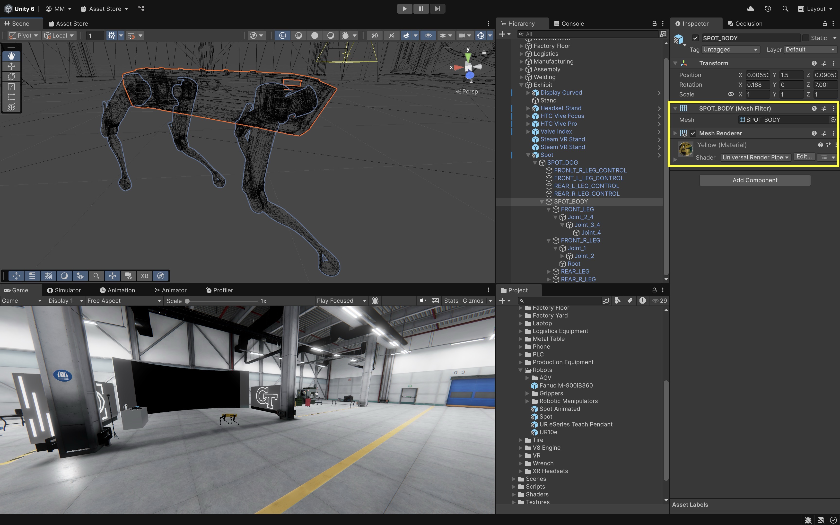
In Unity, a mesh is the geometric structure that defines the shape of a 3D GameObject. Understanding meshes is essential for rendering 3D objects, as shaders, materials, and lighting define how they appear. It is a collection of vertices, edges, and faces that form a 3D object. Each vertex has XYZ coordinates that define its position in space. Meshes are made up of multiple flat polygons that collectively form complex 3D shapes. A mesh is generally structured as follows:
- Vertices: Points in 3D space that define the mesh. Each vertex stores spatial information and sometimes additional data like UV coordinates (for textures).
- Edges: Lines connecting two vertices.
- Faces (Polygons): Enclosed surfaces defined by edges. Typically made of triangles (3 vertices) or quads (4 vertices). For example, the surface of a CNC machine in the manufacturing station may look smooth even though it is made from many flat polygons.
- Normals: Perpendicular vectors to each face or vertex that influence lighting and shading. Normals are crucial in how light reflects off the surface, making them essential for realistic rendering. Meshes appear faceted unless normals smooth their appearance. A sphere, for example, consists of flat polygons but appears round due to normal mapping.
- UV Coordinates: 2D coordinates stored on the mesh that tell Unity how to wrap textures onto the surface. Poor UVs can cause stretching, seams, or inefficient texture use.
- Tangents: Direction vectors used with normal maps so surface details such as scratches, seams, and bumps respond correctly to lighting.
Review this Unity documentation to learn more about mesh components.
Exploring Meshes
To view meshes in wireframe mode:
- Open Unity and navigate to the
Sceneview. - Use the Scene View toolbar’s draw/shading mode controls.
- Select a
Wireframeor wireframe-style draw mode. -
Observe how different objects (e.g., a cube vs. a sphere or the CNC machine in the manufacturing station) have different mesh structures.
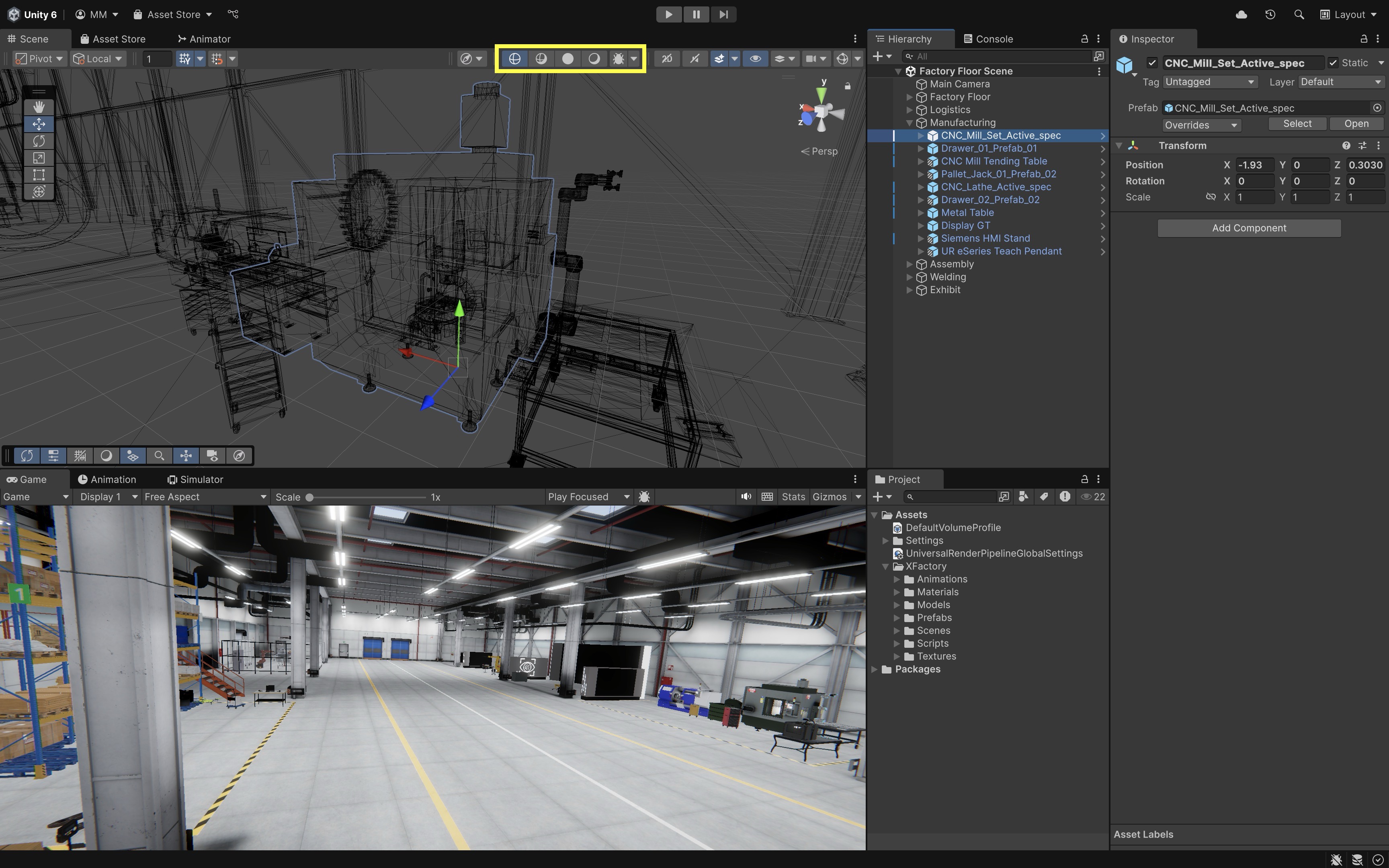
Wireframe mode allows you to see the raw mesh without materials or shading—great for analyzing imported CAD models.
Mesh Filter
The Mesh Filter component stores the mesh asset—the raw vertex, edge, and triangle data that defines the shape of a GameObject. Think of it as the blueprint of the object’s geometry. By itself, a Mesh Filter does not display anything on screen—it only provides the data (typically paired with a Mesh Renderer). A Mesh Filter usually references a shared asset (like a cube, sphere, or imported model). If you assign a different mesh, the object instantly changes shape.
- Select the GameObject.
- In the
Inspector, find theMesh Filtercomponent. -
The assigned mesh is displayed here. You can replace it by selecting another mesh from the project.
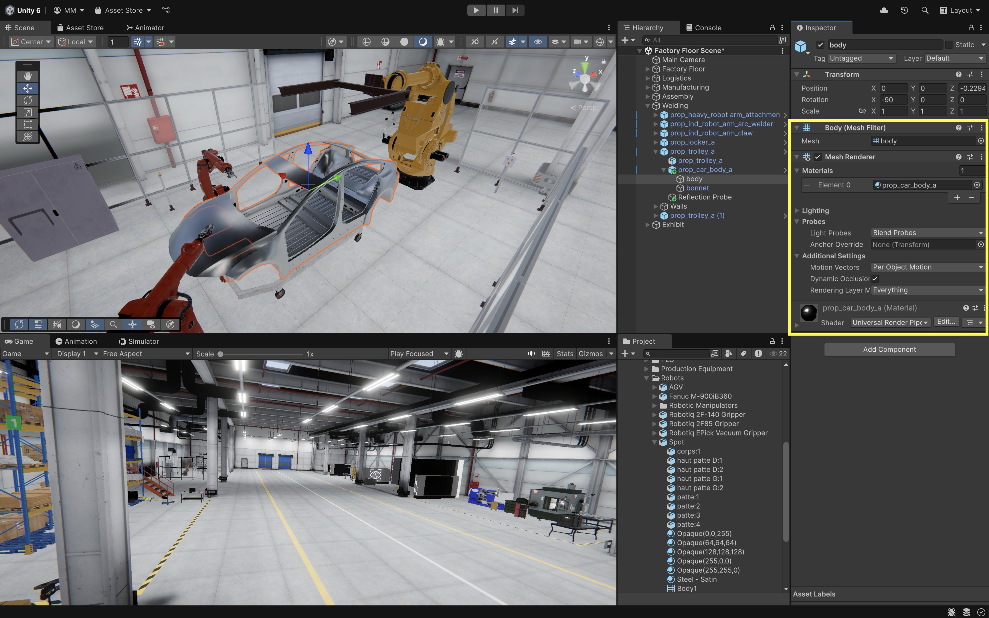
In XFactory, if you are visualizing the car body in the welding station, the
Mesh Filterdefines the geometry of the car’s body panels.
Mesh Renderer
The Mesh Renderer component is responsible for drawing the mesh on screen. It takes the geometry from the Mesh Filter, applies materials and shaders, and makes the object visible under the scene’s lighting conditions.
- The
Materialssection controls surface look (textures, colors, metallic properties). LightingandProbessettings decide how the object responds to scene lights, global illumination, and reflection probes.Shadowscan be enabled/disabled, or set to cast/receive. This affects both performance and visual realism.- Additional settings like
Motion Vectors(for motion blur),Lightmap Static(for baked lighting), andRendering Layer Masks(for selective lighting) give fine-grained control.
Without a
Mesh Filter, theMesh Rendererhas nothing to draw; without aMesh Renderer, theMesh Filterhas nothing to display. Together, they form the backbone of any visible 3D object in Unity.
CAD Models as Meshes
Engineering use cases often require importing components created in CAD software such as SolidWorks or Fusion 360. Unity does not use native CAD solids directly at runtime; CAD data must be converted into polygon meshes that Unity can render. Depending on the workflow, this may happen through interchange formats such as .FBX, .OBJ, .GLTF, or .GLB, through tools such as Blender, or through specialized industrial tools such as Unity Asset Transformer / Pixyz. In XFactory, many components—such as robot arms, CNC parts, drones, and factory equipment—are rendered as optimized meshes. To import a custom mesh into Unity:
- Export the CAD Model from a 3D Software:
.FBX: Best for animation and material support..OBJ: Simple and widely supported..GLTFor.GLB: Lightweight and modern format with good PBR support.
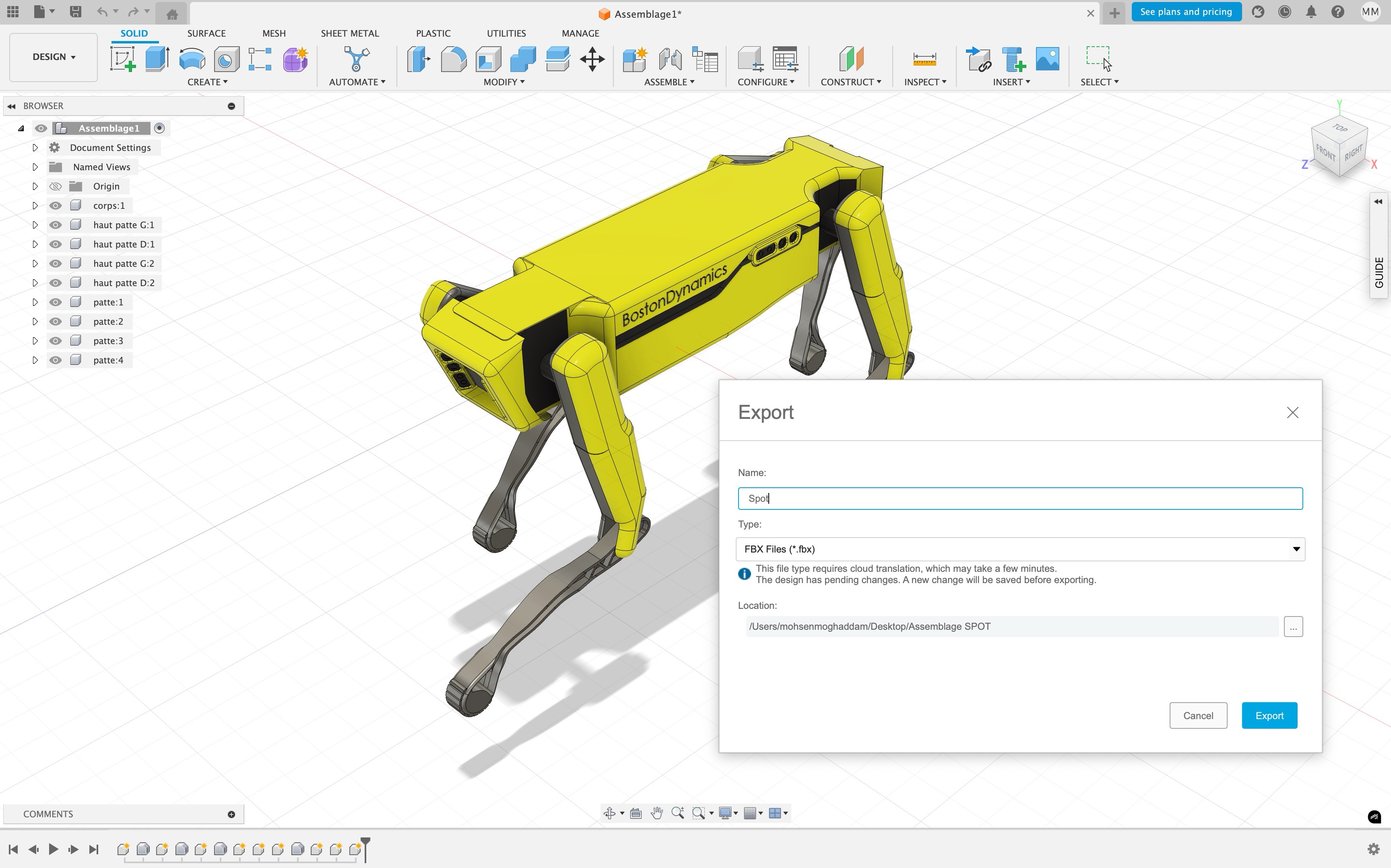
Tools like Blender can be used as an intermediary to convert native CAD files into Unity-friendly formats.
- Import the Model to Unity:
- Place the file into the Unity
Assets > Modelsfolder (or a similar path, to keep things organized). - Select the imported mesh in the Unity Editor and adjust import settings in the
Inspector. - Adjust the
Scale Factorvalue to match real-world units (e.g., set to0.01if importing from millimeters). - Set
Mesh CompressiontoOff,Low,Medium, orHighto reduce file size at the cost of precision; use carefully for detailed models. - Enable
Optimize Meshwhen appropriate to improve rendering performance by reordering vertices and indices for the GPU. - For
Normalssetting, choose betweenImport,Calculate, orNoneto control how lighting and shading are applied. - Set
TangentstoImport,Calculate, orNonebased on whether normal mapping is required for your materials. - Be sure to click
Applyat the bottom of theInspectorafter making changes.
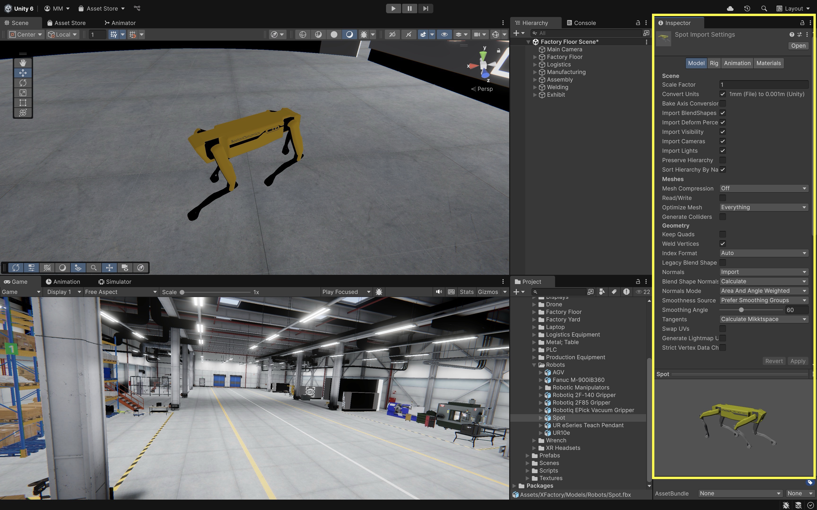
Always verify scale after import. Engineering models may be authored in millimeters, centimeters, meters, or inches, while Unity units are typically treated as meters. Incorrect scale can break lighting, physics, navigation, XR comfort, and interaction distances.
- Place the file into the Unity
Optimizing Meshes
Efficient rendering is crucial for a real-time application like XFactory, especially when dealing with high-resolution engineering models. In VR/AR, it is important to keep the poly count low due to limited GPU resources and strict performance budgets for triangles and polygons. Optimization is not only about polygon count. Rendering cost also depends on the number of materials, draw calls, skinned meshes, transparent objects, texture sizes, shadow-casting lights, and post-processing effects. Below are some optimization tips:
- Reduce Polygon Count: Use decimation or retopology tools in modeling software to lower complexity while preserving shape.
- Use LOD (Level of Detail): Configure Unity to display simpler mesh versions when objects are farther from the camera.
- Use
LOD Groupcomponents: Assign simplified versions of a model so Unity can switch to lower-detail meshes at a distance. - Reduce material slots and repeated draw calls: Combining materials where appropriate, using GPU instancing, and avoiding unnecessary unique materials can improve performance.
- Enable Mesh Compression: Helps reduce file size and memory usage.
- Optimize UV Mapping: Ensures that textures are used efficiently without distortion or overlap.
Tools such as Unity Asset Transformer / Pixyz (for decimating and optimizing CAD and engineering models) are ideal for preparing assets for real-time use. Free alternatives include Blender for manual mesh cleanup. In XFactory, for example, the quadruped robot at the exhibit station may have a high-poly original model. By simplifying its mesh for distant views, XFactory runs smoother on lower-end hardware.
Materials
Materials are essential to Unity’s rendering process, defining how objects appear in a scene. They encapsulate properties such as color, texture, reflectivity, and transparency, and serve as the link between 3D meshes and shaders. Materials simulate the physical appearance of surfaces, helping create visual realism and functional clarity in engineering simulations. In XFactory, the welding station uses high-reflectivity metallic materials for robot arms and the car body, the logistics station includes wood-textured pallets, matte plastic drones, and shiny scanning devices, and the exhibit station includes transparent screen overlays and glass surfaces that use materials with custom transparency settings. Most URP materials use a physically based rendering (PBR) workflow, where surface properties such as base color, metallic value, smoothness, normal maps, and emission help approximate how real materials respond to light.
Review this Unity documentation to learn more about Materials in Unity, such as creating and assigning materials or accessing material properties in a script (which will be covered later).
Default Material
When you create a new 3D object in a URP project, Unity displays it using a default material appearance based on the active render pipeline. In URP, the default appearance is based on the URP Lit shading model. This default material is useful for placeholders during prototyping, but it is not the same as creating your own editable material asset. To customize an object’s appearance, create or assign a material in the Project window.
- Create a 3D Object from the menu:
+>3D Object > CubeorSphere. -
Select the object and inspect the material slot in the
Mesh Renderercomponent. Notice that the object has a default appearance until you assign your own material asset.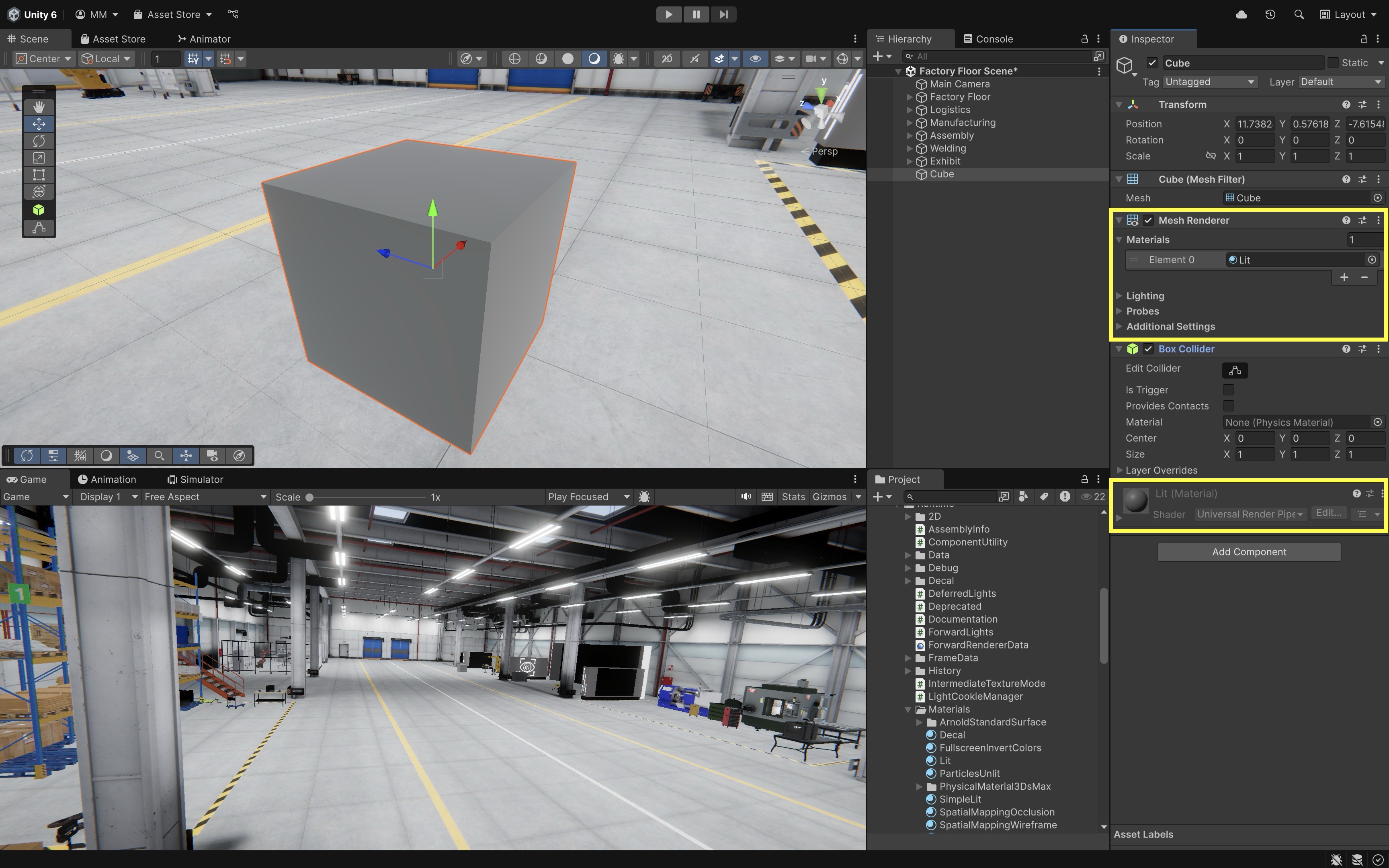
-
Try dragging a different material from the
Project > XFactory > Materialsfolder onto the object in theSceneview to override it.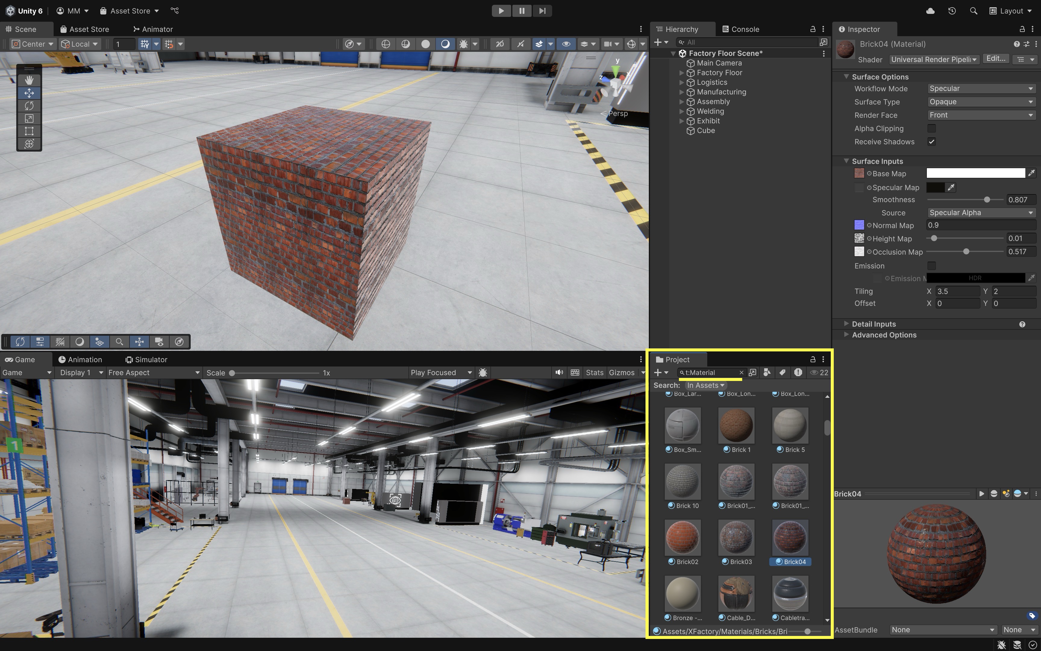
To locate materials, open the
Projectwindow and use the search filter:t:Material. Use scopes likeIn Assets(searches your project files) orIn Packages(includes imported assets and plugins).
Adding a New Material
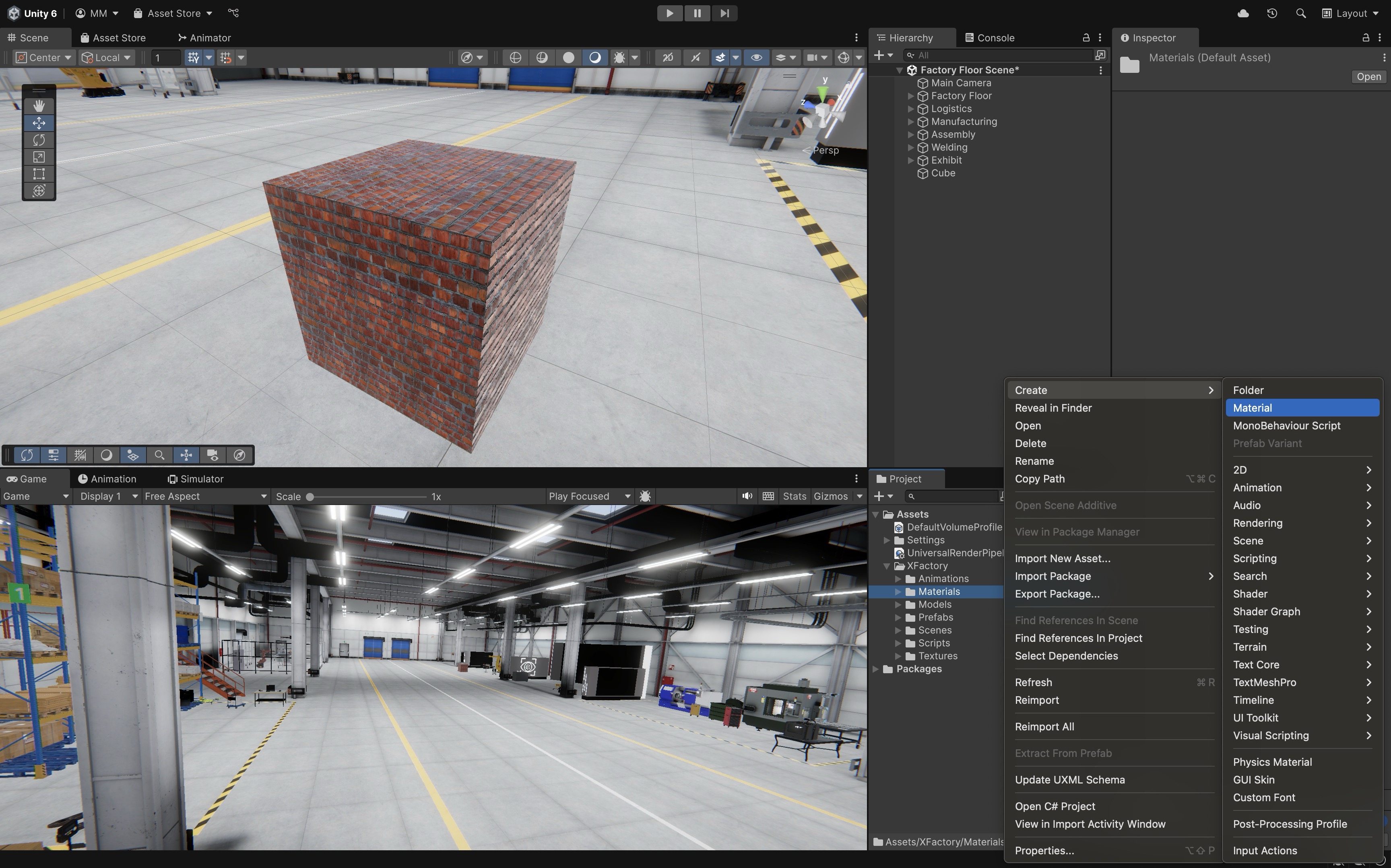
Creating custom materials is essential for adding realism and differentiation between components in engineering scenes. To create a new material:
- Create a
Material:- Navigate to
Assets > XFactory > Materialsin theProjectwindow. - Right-click and select
Create > Material. - Name it descriptively (e.g.,
Box_Metal).
- Navigate to
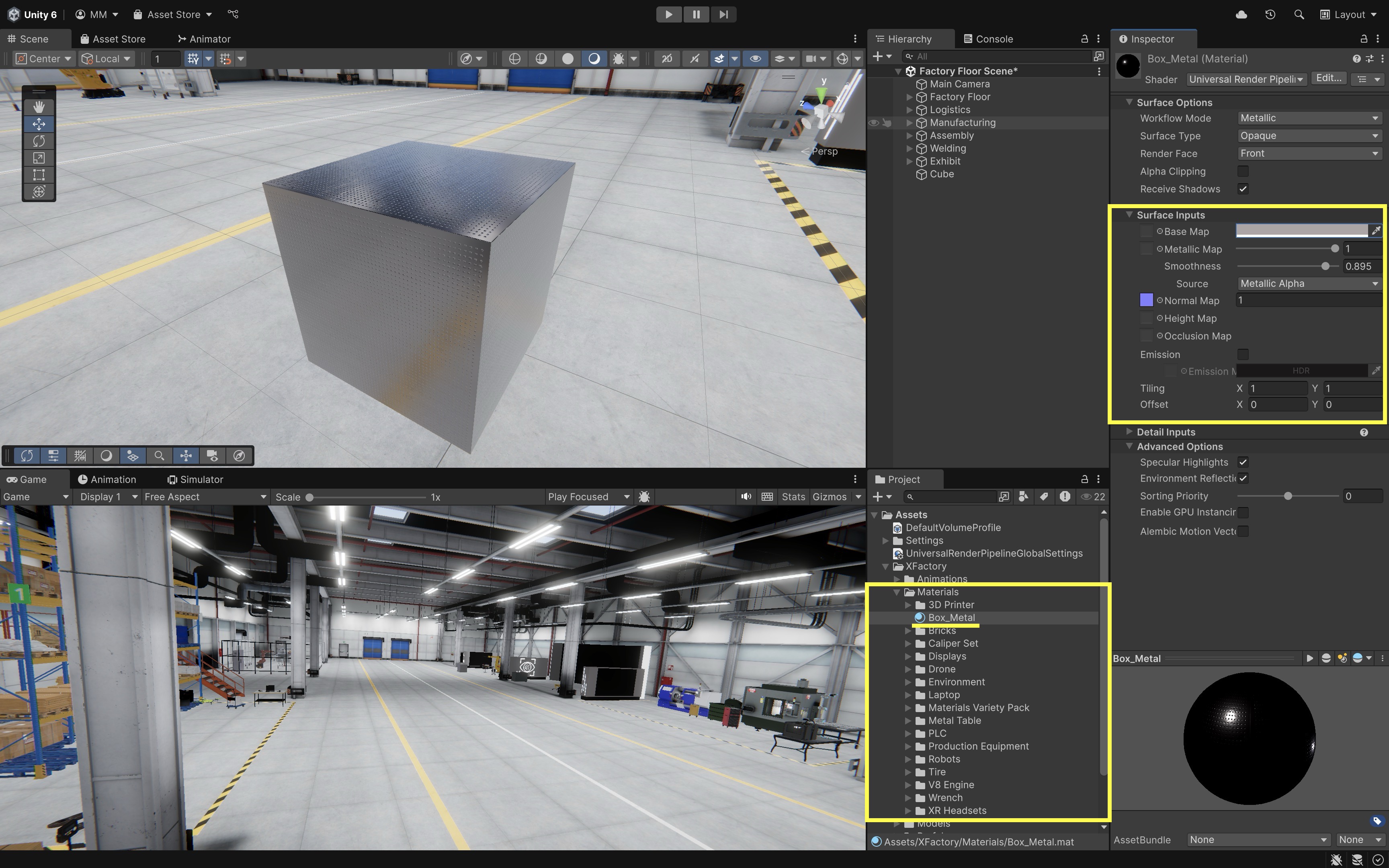
- Configure Material Properties in the
Inspector:Shader: UseUniversal Render Pipeline/Litfor realistic PBR-based shading (orUnlitfor stylized/transparent effects).Base Map: Set the color or assign a texture image (e.g.,.png,.jpg, or.tga).Metallic Map&Smoothness: Use sliders or assign a texture to control surface reflectivity and glossiness.Normal Map: Add a normal map texture to simulate detailed surface bumps and grooves without additional geometry.Height Map: Optional—used for height-based surface effects such as parallax when supported by the shader. In typical URP Lit materials, this creates an illusion of depth rather than changing the actual mesh geometry.Occlusion Map: Optional—enhances depth in crevices using ambient occlusion data.Emission: Use this if the material should glow or emit light.
- Apply the Material to a GameObject:
- Drag & Drop: From
Projectwindow to object inScenewindow. - Inspector Assignment: Drop the material into the
Mesh Renderer > Materialsfield. - Object Selector: Click the
⊙icon next to the material field and pick from the list. - Copy from Another Object: Drag a material thumbnail from one object’s
Inspectorto another.
Materials in Unity are shared assets. This means any changes made to a material will affect all objects using it. To create variations without affecting the original, duplicate the material by clicking on it and pressing Ctrl+D (Cmd+D on Mac). If you drag the same material onto multiple objects, editing that material later changes all of those objects. Duplicate the material before making object-specific variations such as different colors, labels, or roughness values.
- Drag & Drop: From
Fixing Magenta Materials
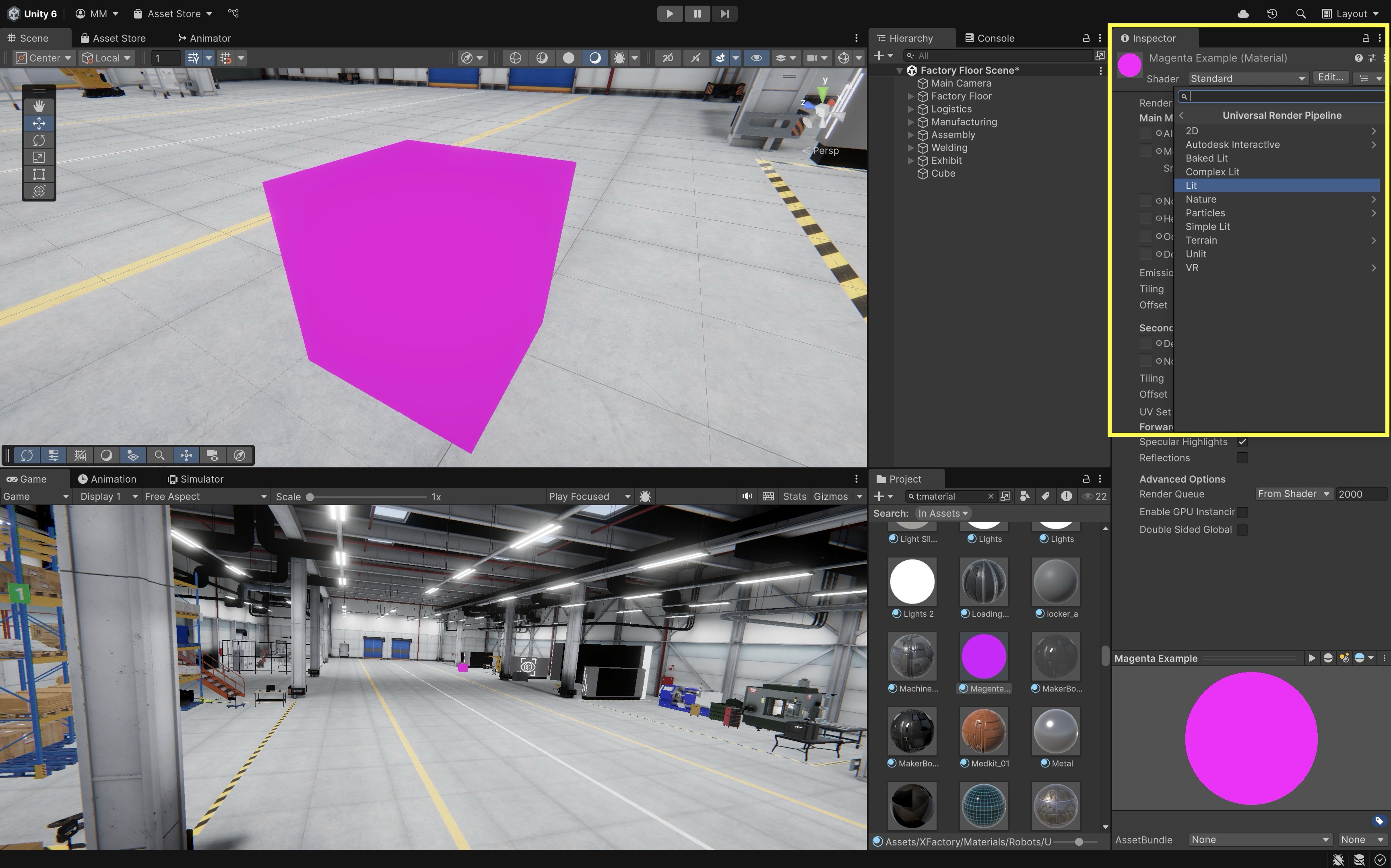
Bright magenta materials are Unity’s way of indicating a problem—most commonly a shader compatibility error. This frequently occurs when you import new assets that use shaders incompatible with your project’s current render pipeline (e.g., URP vs. Built-in). The material is likely referencing a shader that no longer exists or isn’t supported, resulting in Unity rendering it as magenta to signal the issue. You can fix magenta materials in two different ways:
A material is only as portable as its shader. If an asset was created for Built-in or HDRP, assigning it to a URP project may require a URP-compatible shader or a material conversion step.
- Manual Fix:
- Select the affected GameObject.
- In
Inspector, change the shader toUniversal Render Pipeline > Lit.
Before running automatic conversion tools, save or back up the project. Render-pipeline conversion can change many material assets at once.
- Automatic Fix via
Render Pipeline Converter:- Open
Window > Rendering > Render Pipeline Converter. - Select
Built-in to URP. - Enable the
Material Upgradeoption. - Click the relevant initialize/convert option shown by the Render Pipeline Converter.
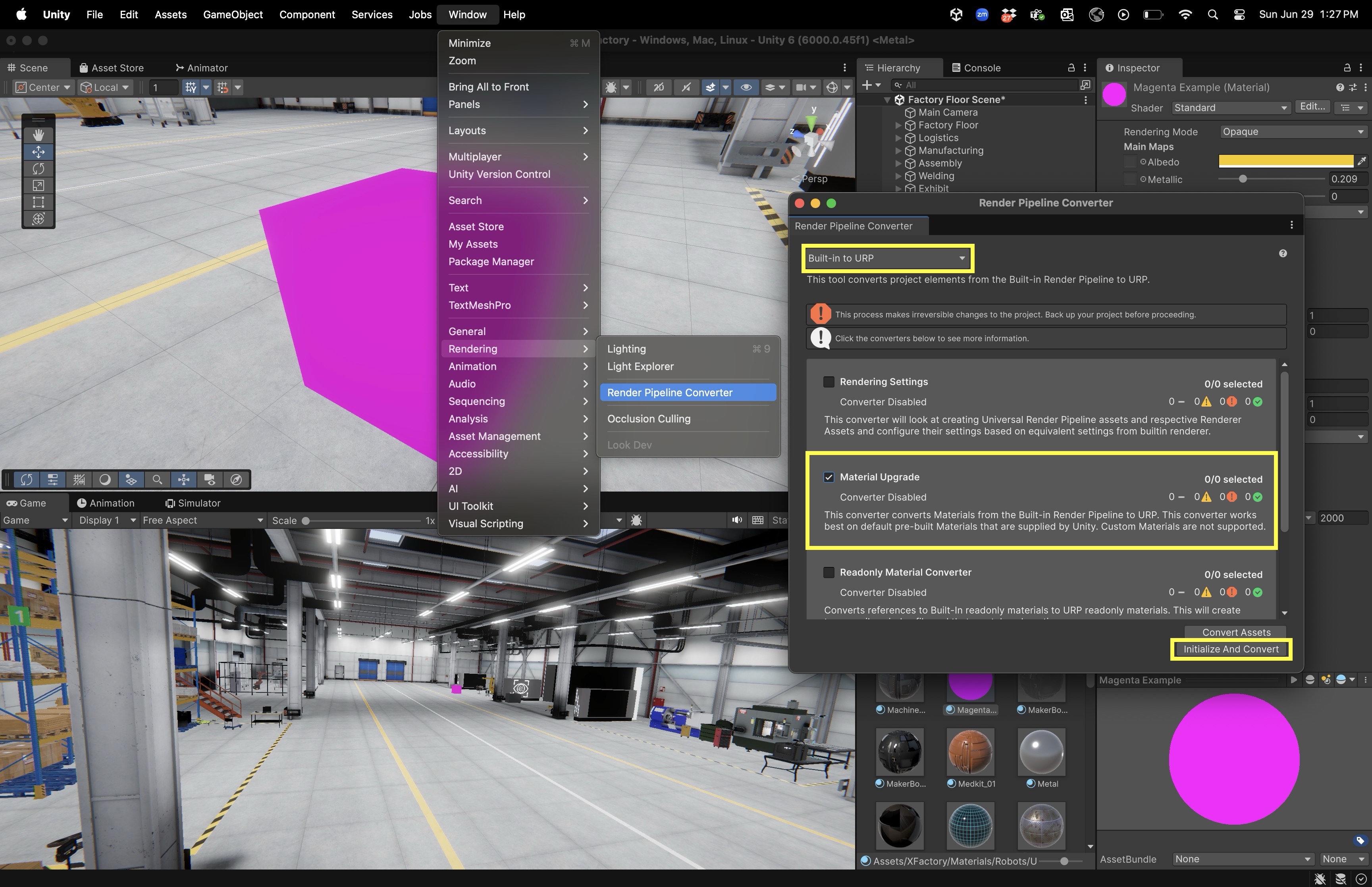
This can fix many standard Built-in pipeline materials so they display correctly in URP. The converter works best for standard Built-in pipeline materials. Custom shaders, third-party shader graphs, transparent materials, or special effects may still require manual shader replacement or material recreation.
- Open
Textures
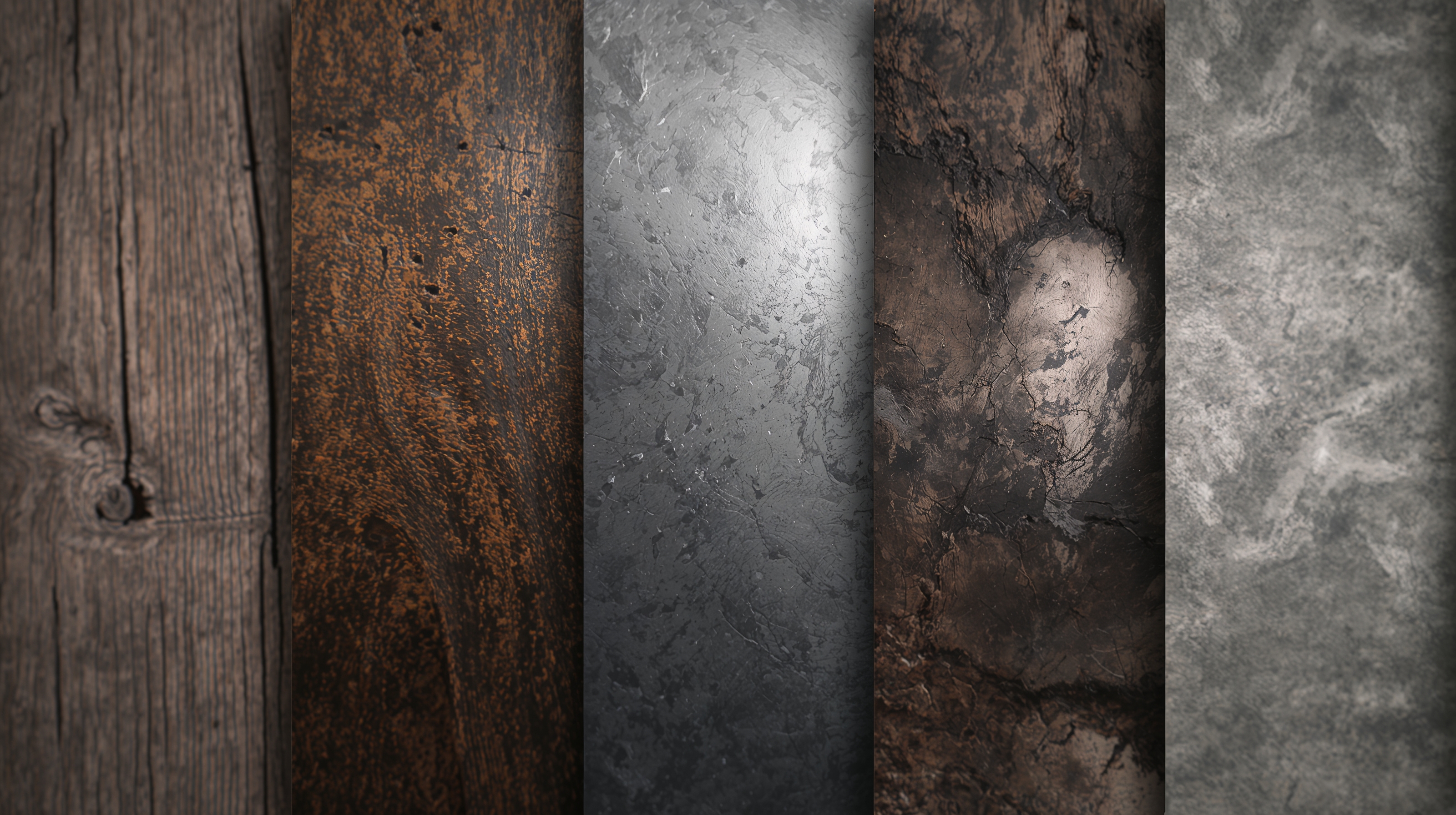
Textures are 2D images applied to 3D models to simulate surface detail and realism. While materials define how an object interacts with light, textures provide the visual content that brings surfaces to life—like rust, grain, wear, paint, or logos. Textures are typically assigned through the Base Map of a material, but may also be used in other properties like Normal Map, Metallic Map, and Occlusion Map.
In XFactory, textures help communicate function and realism—for instance, wood grain textures on logistics pallets, scratch textures on welding station robots, and touchscreen interface graphics on tech station panels.
Types of Textures
Different types of texture maps simulate specific surface properties:
Base Map(Albedo): The primary color and surface detail. Think of it as “paint on a surface.” Used for most visual appearances.Normal Map: Simulates bumps and fine surface details like scratches, tread patterns, weld seams, or brushed metal.Height Map: Adds the illusion of depth by offsetting surface detail when supported by the shader. In typical URP Lit materials, height maps are used for parallax-like effects rather than changing the actual mesh geometry.Metallic Map: Dictates which parts of the object act metallic vs. non-metallic. Black = non-metal, white = metal.Smoothness/Roughness Map: Controls gloss and light scattering. In Unity’s URP Lit workflow, smoothness is commonly stored in a channel of the metallic or mask texture. Roughness maps from other tools may need to be inverted because roughness and smoothness are opposites.-
Occlusion Map: Enhances shadows in crevices and seams for depth perception.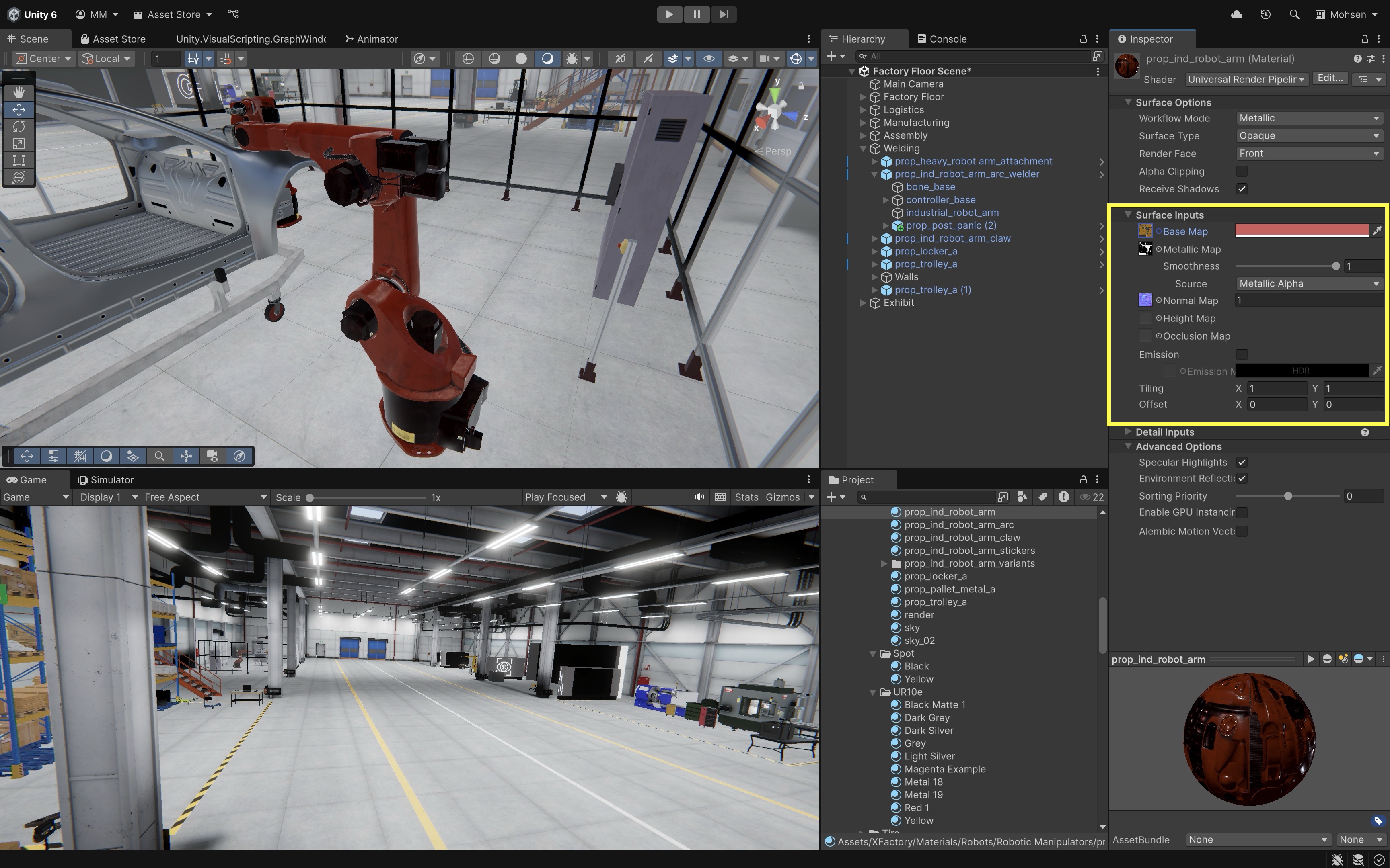
The robotic arms in the welding station use three key textures to achieve a realistic appearance: the
Base Mapprovides the core color and surface details, theMetallic Mapcontrols how reflective and metallic different parts of the surface appear, and theNormal Mapsimulates fine bumps and panel seams without adding extra geometry.
Applying Textures to Materials
Textures are usually applied through the Material Inspector. To apply a texture:
- Select a material (e.g.,
prop_ind_robot_arm). - In the
Inspector, find theBase Mapslot (or other maps as necessary). - Click the small circle
⊙next to the texture field. - Choose a texture from the list or drag a texture file into the field.
-
Preview changes in the
SceneorGameview.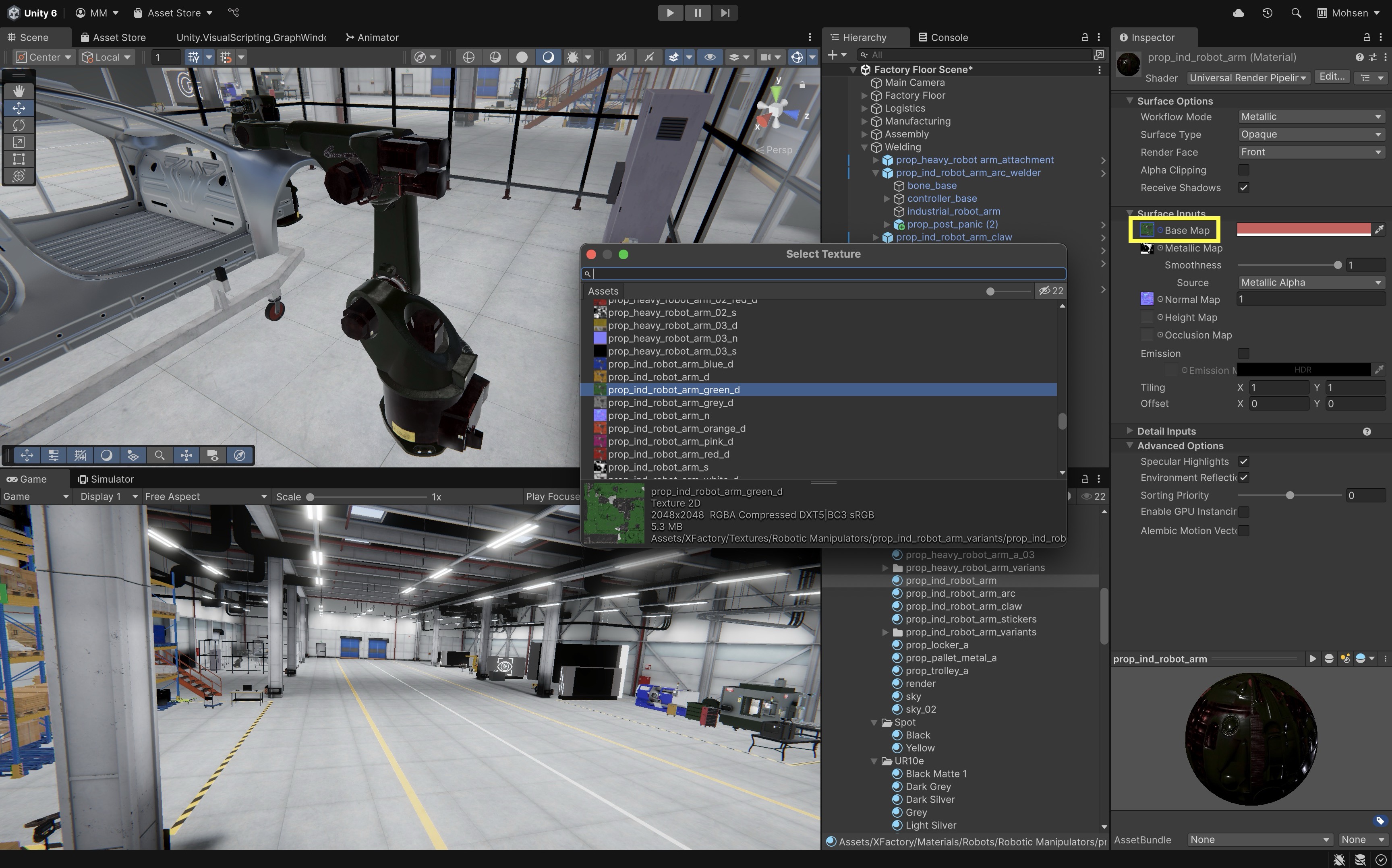
Using Imported Textures
Unity supports various image formats such as .PNG, .JPG, and .TGA. To import textures:
- Import the Texture:
- Drag the image file into the
Assets > XFactory > Texturesfolder (or any organized subfolder in your project). - Select the texture and adjust
Import Settingsin theInspector. - Set
Texture TypetoDefaultfor most uses. - Set
Texture TypetoNormal mapfor normal-map textures so Unity interprets the data correctly. - Enable
sRGB (Color Texture)forBase Map; disable for masks or data maps. - Set
Alpha Sourceappropriately for transparency needs. - Set
Wrap ModetoRepeat(for tiling surfaces like floors) orClamp(for UI graphics). - Set
Filter ModetoBilinearorTrilinearfor smooth transitions.
- Drag the image file into the
- Assign the Texture to a Material:
- In the
Inspector, drag the texture into the appropriate field. - Use the texture as a
Base Mapfor the object’s surface color and pattern. - Assign it to the
Normal Mapslot (if a normal texture is available) to simulate fine surface detail without extra geometry. - Use grayscale textures as a
Metallic Map,Roughness Map, orOcclusion Mapto control reflectivity, surface roughness, and ambient shading. For instance, a cardboard texture applied to a cube’s material (Base Map) to resemble a cardboard box should useRepeatwrap mode andBilinearorTrilinearfiltering to ensure the texture tiles seamlessly across all sides and maintains visual sharpness at various viewing angles and distances.
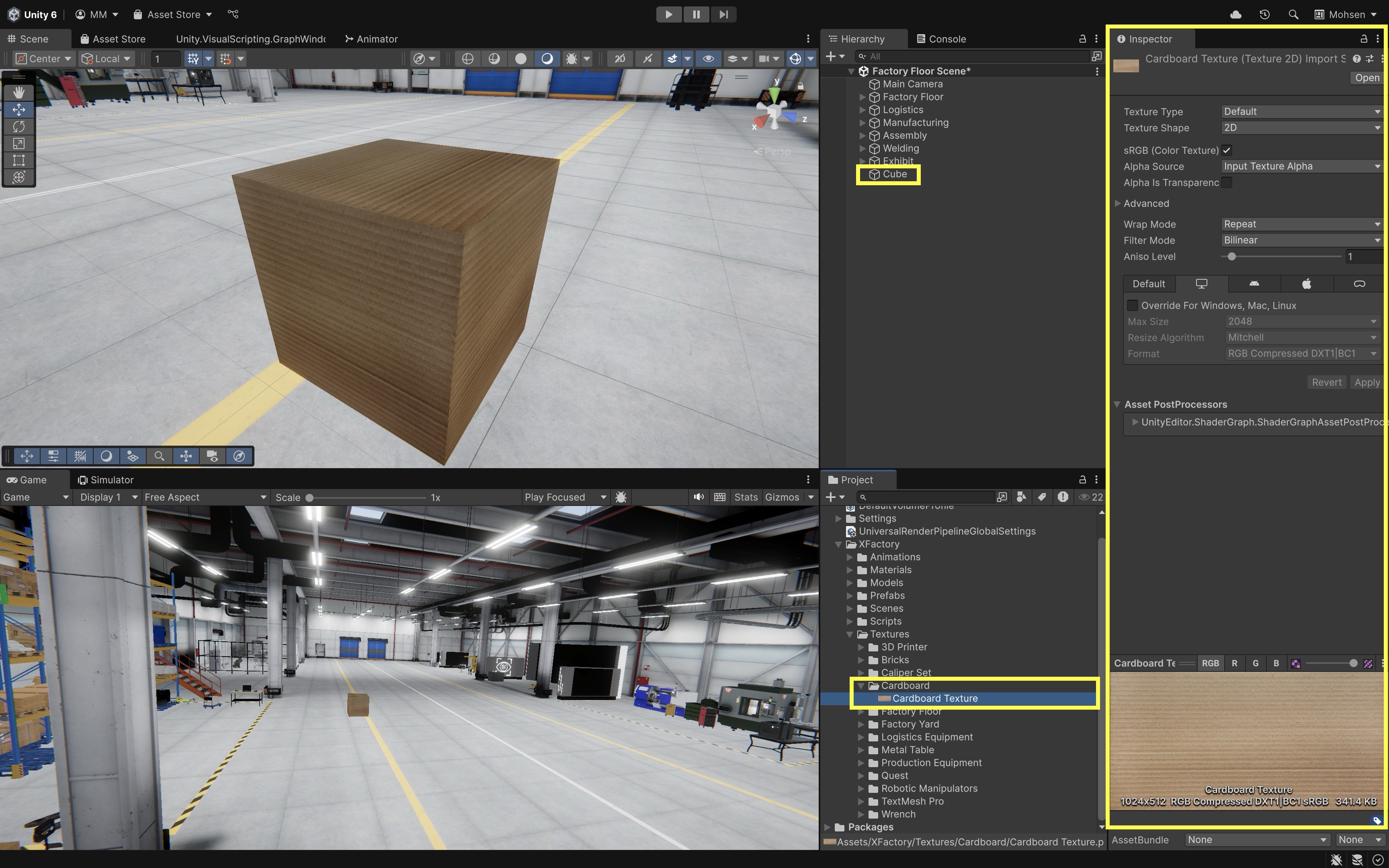
Higher-resolution textures provide more detail but can affect performance. For XR applications in engineering simulations, balance is key. For example, 2K (2048x2048) is suitable for mid-size objects (e.g., drones, carts), 4K (4096x4096) is best for close-up views (e.g., HMI screens), and 512 or 1K can be used for background or repeated elements (e.g., storage boxes). Also check texture
Max Sizeand compression settings in the Inspector. Large uncompressed textures can quickly increase memory use, which is especially important for standalone VR and mobile AR. - In the
Shaders
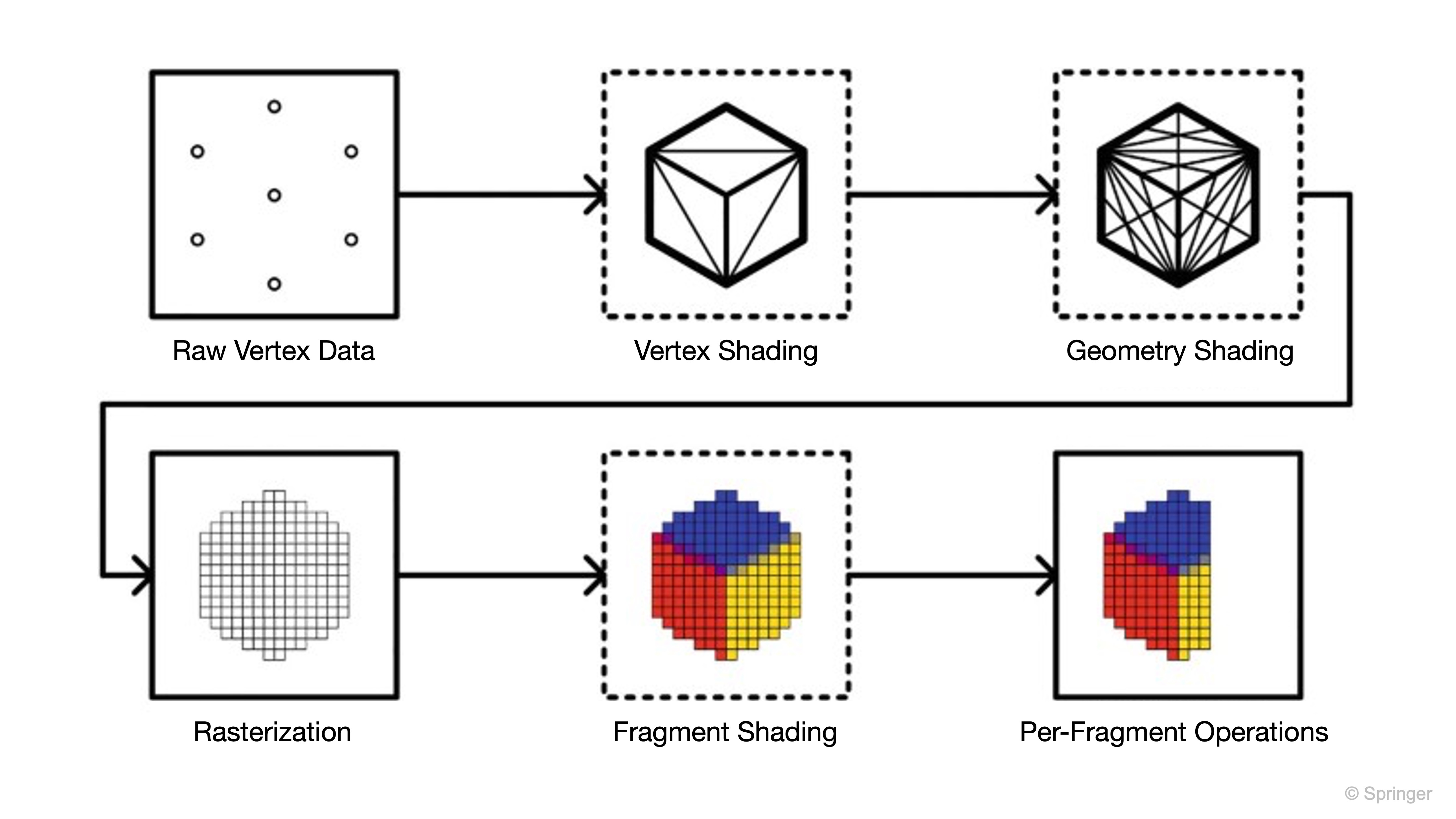
A shader is a GPU program that determines how geometry and pixels are rendered. In Unity, a material references a shader, and the shader exposes the properties—such as color, texture maps, smoothness, transparency, and emission—that the material can use. Shaders are closely tied to the active render pipeline, so a material created for Built-in, URP, or HDRP may not work correctly in another pipeline without conversion. At a high level, shaders operate through these stages:
- Vertex Shading: Processes each vertex, transforming mesh positions and preparing data such as normals, UVs, and colors for later stages.
- Rasterization: Converts triangles into fragments, which are potential pixels on the screen.
- Fragment/Pixel Shading: Calculates the final visible color of each fragment using textures, lighting, material properties, shadows, and transparency rules.
- Per-Fragment Operations: Performs depth testing, stencil testing, blending, and other final operations before writing pixels to the framebuffer.
In Unity, “shading” means evaluating how geometry or pixels should look on screen, whether that involves positions, colors, lighting, or other attributes. Shaders are like a group of painters working on a mural: the vertex shaders are the sketch artists who lay out and adjust the framework of shapes, deciding where edges and corners go, while the fragment (pixel) shaders are the painters who fill in every patch with color, shading, and texture, making the final image come to life under light. Review this e-book to learn how to create shaders and visual effects in Unity.
Shaders in URP
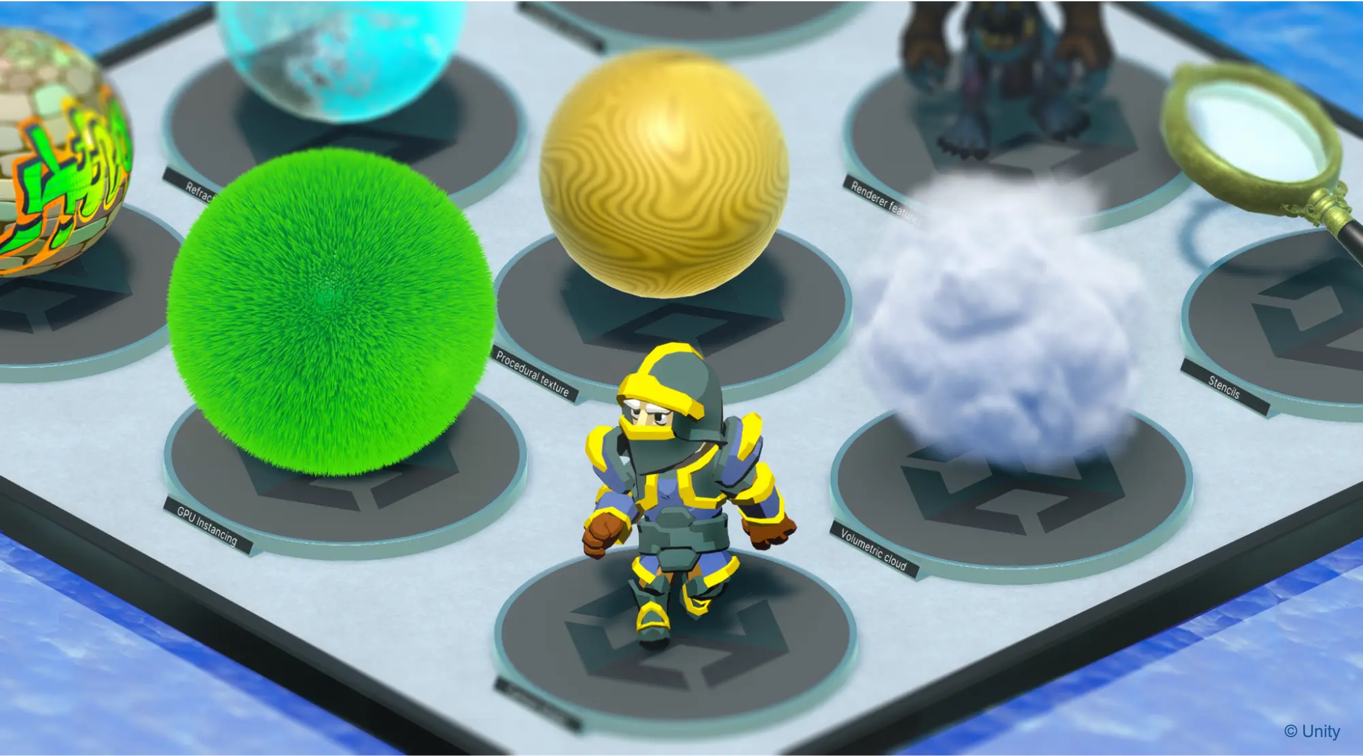
Unity’s Universal Render Pipeline (URP) includes a set of optimized shaders that support both high-quality visuals and real-time performance—ideal for XR environments deployed across various devices.
Lit: PBR shader for most real-world materials such as metal, plastic, wood, concrete, and painted surfaces.Simple Lit: Lower-cost, non-PBR shader useful when performance is more important than physically based realism.Complex Lit: Higher-cost shader for advanced materials such as clear coat effects; avoid on low-power XR devices unless needed.Baked Lit: Optimized for objects that rely mainly on baked lighting and lightmaps rather than real-time lighting.Unlit: Ignores scene lighting; useful for icons, labels, UI-like elements, debug visuals, and stylized overlays.Terrain Lit: Used for Unity Terrain materials.Particles(Lit,Simple Lit,Unlit): Used for visual effects such as welding sparks, smoke, dust, or trails.- Sprite shaders: Useful for 2D UI, icons, and overlay elements, but less central to the 3D/XR rendering workflow covered in this session.
Use
URP/Lit Shaderfor reflective surfaces like polished metal surfaces,Unlit Shaderfor fixed-color UI overlays on control screens, andParticles > Litfor real-time welding sparks in the welding station.
Exploring URP Shaders
You can experiment with URP shaders directly in the Unity Editor:
- Select a 3D GameObject in the Scene (e.g., a robotic arm).
- In the
Inspector, find theMesh Renderercomponent and locate the assigned material, or select the material asset directly in the Project window. - Locate the
Shaderfield at the top of the material settings. - Open the shader dropdown and navigate to
Universal Render Pipeline, then choose a shader such asLit,Simple Lit,Complex Lit, orUnlit. -
Observe how different shaders affect lighting, transparency, and reflectivity.
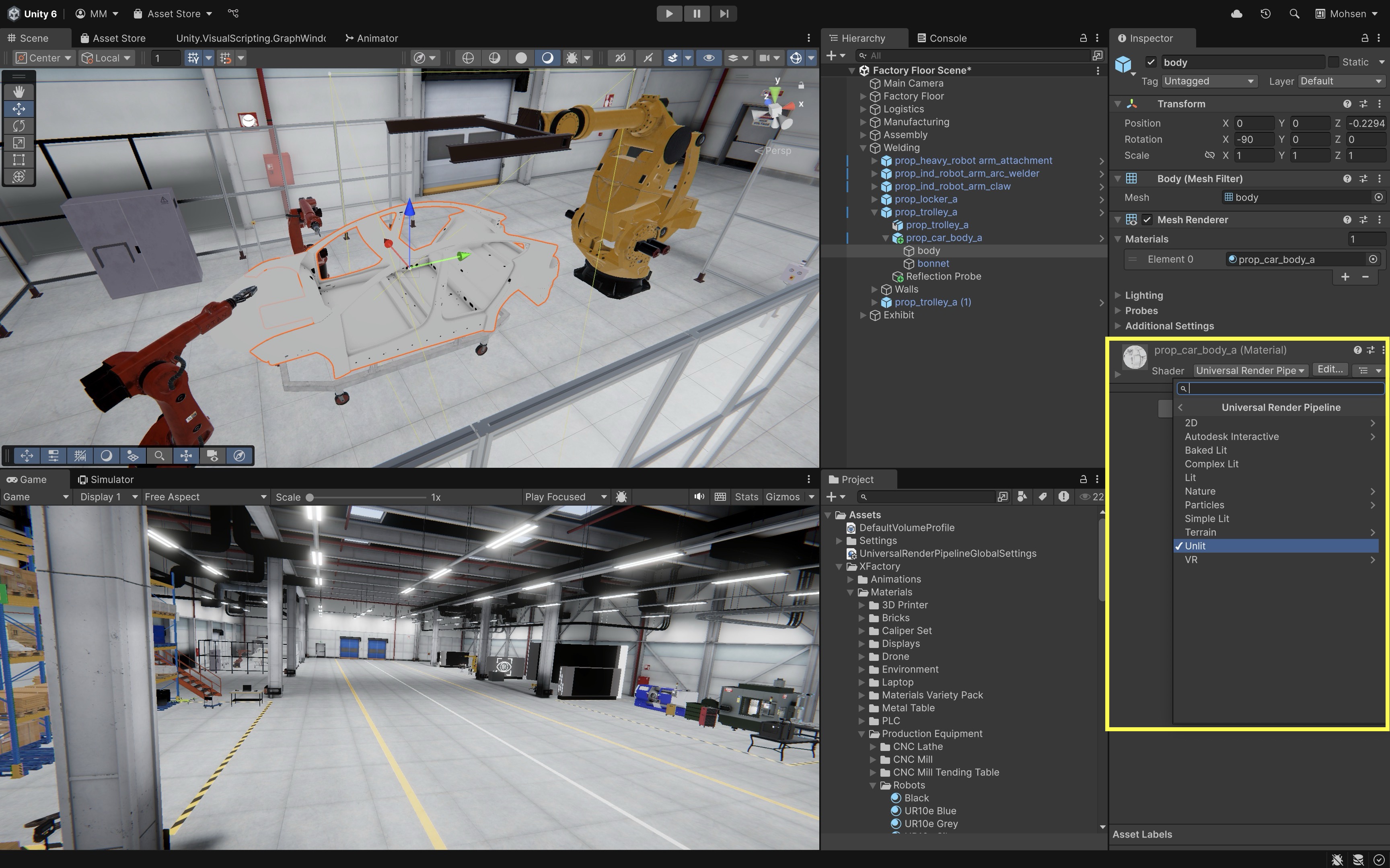
Try switching the
Lit Shaderof the car body in the welding station to anUnlit Shader. You will see the difference in how light interacts with reflections.
Lighting
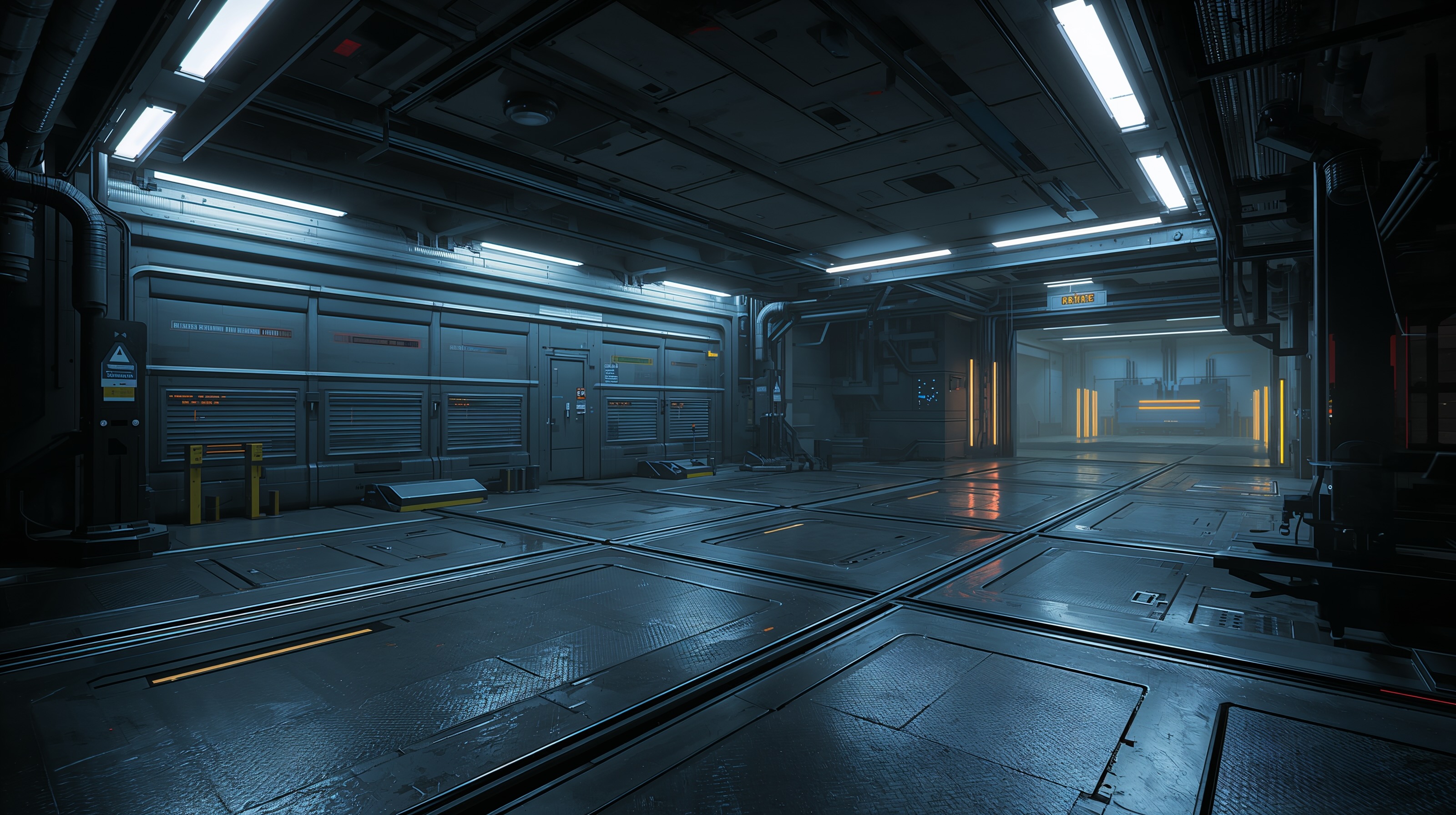
Lighting is a foundational component of rendering in Unity. It defines how objects appear in a scene, influences performance, and contributes significantly to realism and usability in XR environments. Lighting plays a critical role in both the visual quality and performance of a Unity scene. Thoughtful lighting design enhances clarity, immersion, and usability in interactive environments.
- Clarifying Spatial Relationships and Depth: Well-placed lighting helps users distinguish between foreground, background, and overlapping objects, making navigation more intuitive.
- Highlighting Active vs. Inactive Elements: Dynamic lighting can be used to indicate the status of scene elements—e.g., a CNC machine might glow or cast a light when powered on, drawing the user’s attention.
- Simulating Time-of-Day Conditions: Lighting setups can mimic morning, midday, or evening environments, contributing to narrative context or mood.
- Improving Realism: Realistic lighting and shadowing reinforce depth perception and material authenticity, especially when simulating industrial or physical environments.
- Managing Performance: Lighting affects rendering complexity. Real-time shadows, global illumination, and baked lighting all carry different performance costs—crucial considerations for VR or AR applications where frame rate is critical.
In XR, lighting must be designed with a performance budget. Real-time shadows, many overlapping lights, high-resolution shadow maps, transparent materials, and post-processing can reduce frame rate. Prefer baked lighting for static environments and reserve real-time lights for objects or effects that truly need to change at runtime.
Light Types
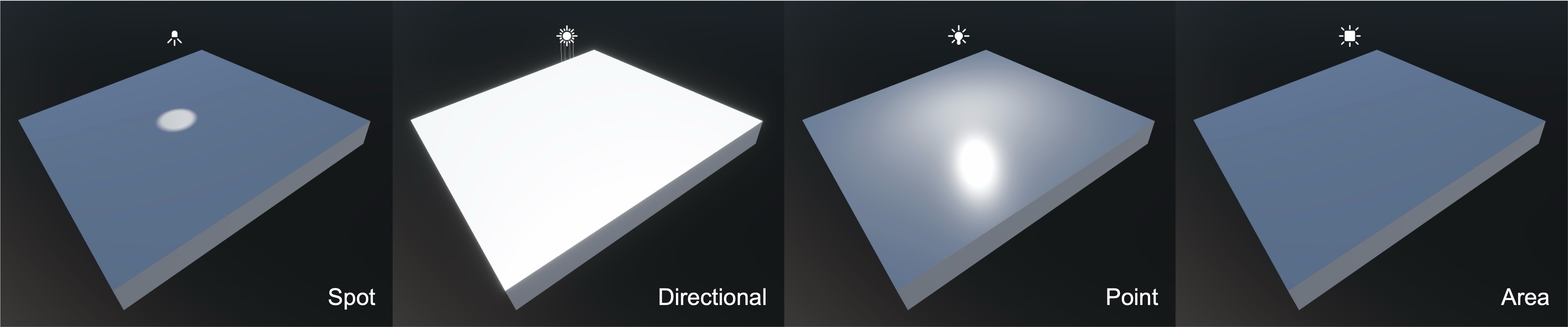
Unity supports several core light types, each serving a unique role in shaping how environments are lit—especially important in engineering visualizations like factory simulations.
- Directional Light simulates sunlight or other distant light sources by casting parallel rays across the entire scene, regardless of distance or size. This is ideal for global lighting, such as simulating daylight over the exterior of a factory or providing uniform light coverage across large workspaces.
- Point Light emits light in all directions from a single point in space, similar to a bare bulb. It is commonly used for overhead lights, indicator LEDs on mobile robots, or illuminating small localized areas.
- Spot Light projects a focused cone of light in a specific direction, allowing for targeted illumination. This type is effective for robotic weld torches, inspection lamps, or simulating focused task lighting in work cells.
- Area Light emits light from a rectangular or disc-shaped surface and is typically used for soft, realistic baked lighting. Real-time support and behavior vary by render pipeline and target platform, so for this course treat area lights primarily as baked lighting tools. Use area lights to simulate architectural wall panels or soft, diffuse lighting in fixed installations.
- Ambient Light provides low-level, omnidirectional illumination across the entire scene, without casting shadows. This helps avoid harsh contrast and can simulate subtle background lighting in large factory halls or uniformly lit interiors.
Choosing the right light type is essential for balancing visual realism with performance, especially in XR environments.
Lighting Behavior
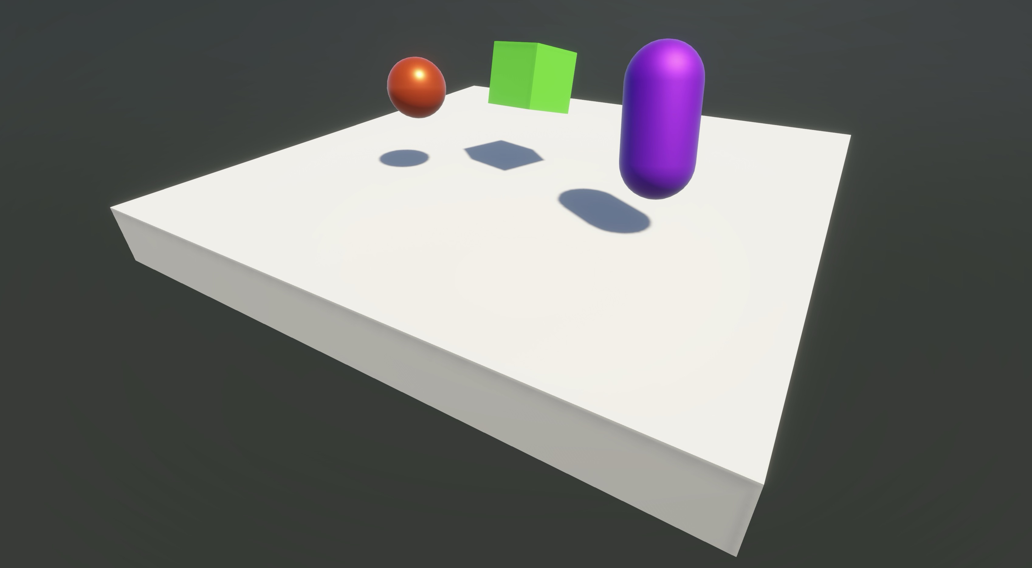
Light in Unity simulates how it interacts with real-world surfaces:
- Reflection: Smooth surfaces (e.g., polished robot arms) reflect light directionally.
- Transparency and Refraction-like Effects: Transparent materials such as safety glass can reveal objects behind them and may simulate refraction-like distortion depending on the shader and render pipeline. True physically accurate refraction is more limited and expensive, especially in real-time XR.
- Shadows: Realistic occlusion improves depth perception and immersion. Main shadow types include
Hard(crisp, defined edges),Soft(smoother, more natural shadows),Realtime(for dynamic objects and lighting), andBaked(for static scenes with better performance). - Emission: Surfaces can appear to glow—useful for status indicators, screens, and warning lights. Emissive materials do not automatically illuminate other objects in real time unless supported by the lighting setup, baking workflow, or additional lights.
Shadows enhance realism but impact performance. Use shadow-casting lights sparingly, and tune
Shadow DistanceandResolutionunderProject Settings > Quality.
Lighting Source
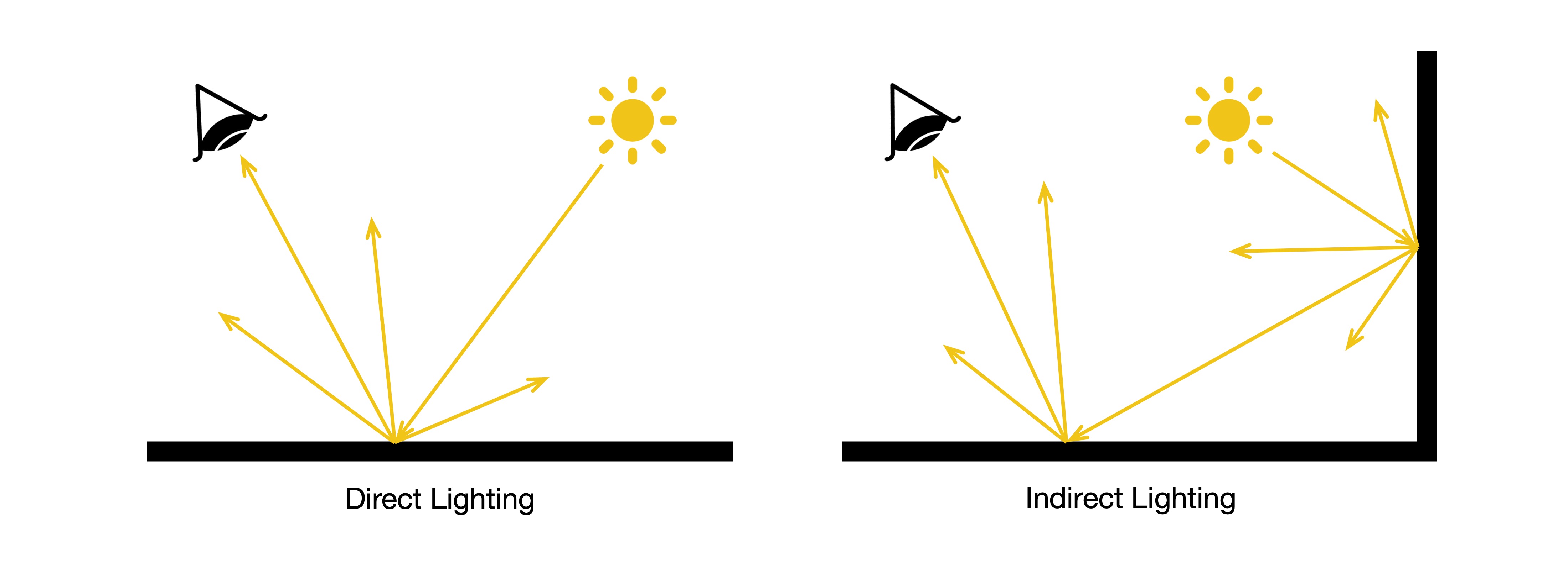
Unity supports Realtime Lighting (best for dynamic objects but costly in XR), Baked Lighting (ideal for static elements with no runtime cost), and Mixed Lighting (a balance that bakes static geometry while allowing dynamic objects to cast realtime shadows). For this course’s URP-based XR workflow, rely primarily on baked GI, lightmaps, and light probes for static interior environments like factory floors, walls, and machinery. Mixed lights are useful but not “free.” They can still involve real-time lighting or shadow costs depending on the lighting mode, so use them carefully in XR scenes.
-
Direct Lighting: Direct light comes straight from a light source to a surface, producing strong highlights, defined shadows, and clear visibility of object contours. It is often used for attention and focus (e.g., a welding torch, floodlight on a machine, or a spotlight over an HMI).
-
Indirect Lighting: Indirect lighting results from light bouncing between surfaces, adding soft shadows, ambient fill light, and subtle color bleeding from surrounding materials (e.g., a red machine reflecting onto the floor). This contributes heavily to immersion and realism, especially in interior factory scenes with metallic or glossy materials.
-
Global Illumination (GI): GI simulates how light scatters and bounces across a scene, adding depth and realism.
- Baked GI: Precomputed lighting stored in lightmaps and light probes; ideal for static environments such as factory floors, walls, and fixed machinery.
- Mixed Lighting: Combines baked lighting for static geometry with some real-time lighting or shadows for dynamic objects, depending on the selected lighting mode.
- Realtime indirect lighting: More expensive and pipeline-dependent; this course should rely primarily on baked GI and light probes for XR-friendly performance.
- Progressive Lightmapper: Unity’s tool for baking GI, offering GPU/CPU-based solutions for faster iteration.
Review this Unity documentation to learn more about light modes in Unity.
Configuring Lights (Direct)
- Add a Light:
- In the
Hierarchy, use the+menu orGameObject > Lightto add a light type such asDirectional,Point, orSpot. - The light appears in the
Sceneview.
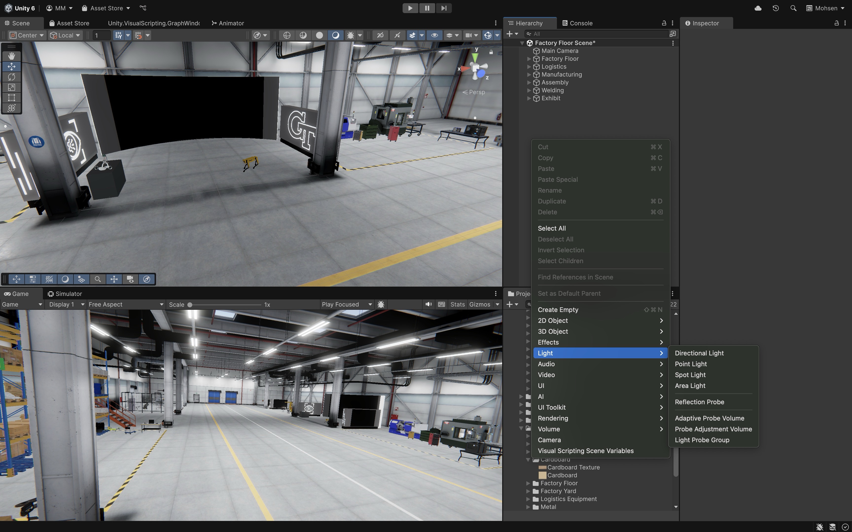
- In the
- Configure the
Light:Type: Choose the light type (Directional,Point,Spot,Area) based on the lighting scenario or physical source you are simulating.Mode: Select how the light is calculated (Realtime,Mixed, orBaked).Light Appearance: Adjust settings like cookie textures (to simulate patterned light), flare, or bounce intensity to influence the visual feel of the light.Color: Choose a color that suits the lighting context—use accurate, neutral tones for realism or warmer/cooler hues for mood and contrast.Intensity: Controls how bright the light appears; tune it to match real-world brightness or to ensure visibility in dark areas.Range: Sets the distance the light reaches (relevant forPointandSpotlights); larger values illuminate more area but may affect performance.Culling Mask: Defines which layers the light affects—useful for optimizing performance or isolating lighting to specific objects (e.g., only affecting machinery, not background props).Shadow Type: Choose whether the light casts hard shadows, soft shadows, or no shadows, depending on the desired realism and performance budget.
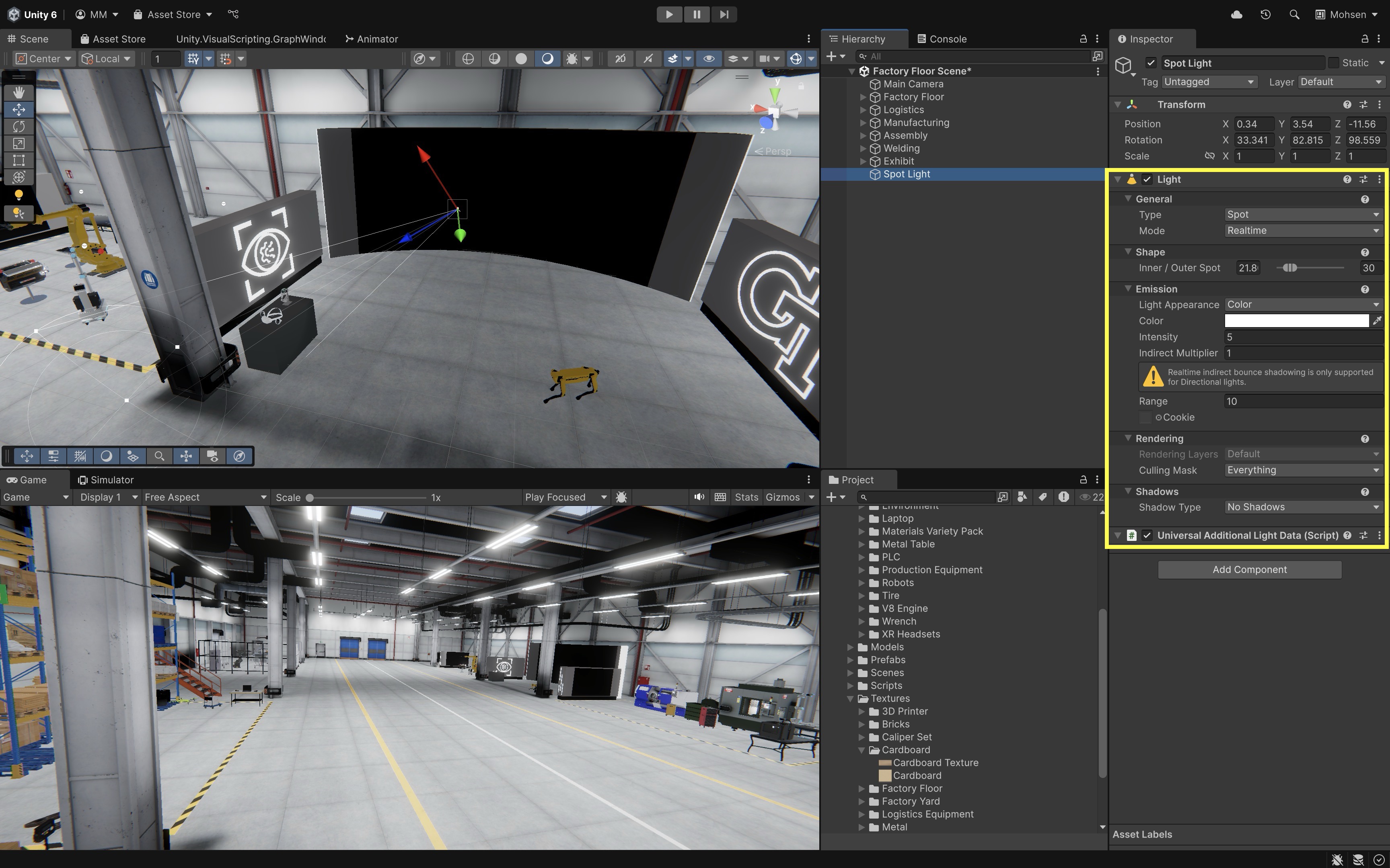
The exact Light Inspector fields may vary depending on the active render pipeline, light type, and whether the light is Realtime, Mixed, or Baked. Use
Spotlights to mimic focused, high-intensity work lights on the XR headset stand.
Ambient Lighting (Indirect)
Ambient lighting provides overall scene brightness and ensures no object is left in complete darkness. To configure:
- Open
Window > Rendering > Lighting. - Go to the
Environmenttab. - Set
Ambient Source:Skybox: Uses the sky environment (most realistic).Gradient: Blend from sky to ground (efficient).Color: Uniform ambient light.
- Tweak the
Intensity Multiplierfor brightness. -
If you are using baked lighting, click
Generate Lightingto bake and preview the result. If you are only changing real-time environment lighting, the scene may update without a bake.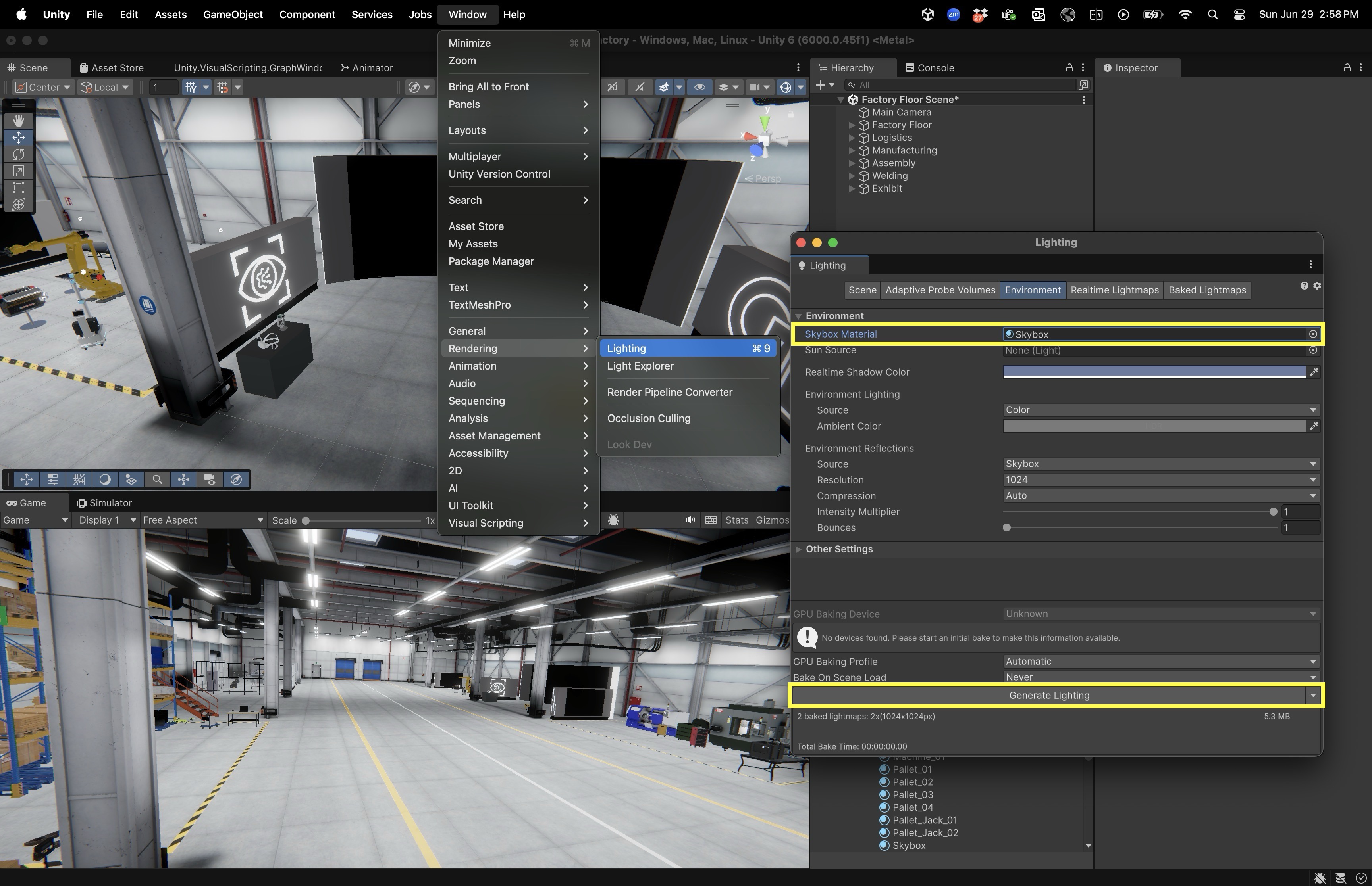
Use ambient lighting to softly illuminate the logistics station’s walls without placing individual light sources.
Light Probes (Indirect)
While baked lighting works well for static objects, dynamic objects—such as moving robots or mobile equipment—need additional data to appear realistically lit in baked environments. Light Probes address this by storing information about indirect lighting (light bounced from nearby surfaces) and applying it to dynamic GameObjects. Light probes do not replace real-time lights. They help dynamic objects receive believable baked indirect lighting as they move through a baked scene. To use light probes:
- In the
Hierarchy, click+ > Light > Light Probe Group. - Position probes around areas where dynamic objects operate.
-
Bake lighting again (
Lighting > Generate Lighting).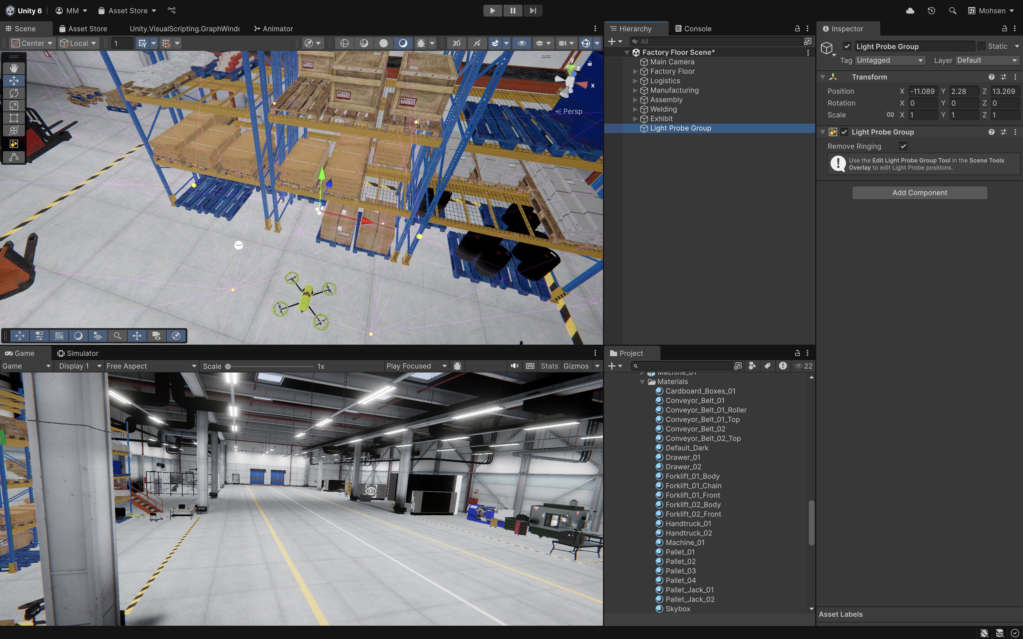
Use Light Probes along forklift routes or drone pathways in XFactory to ensure lighting stays consistent as they move through the environment. Baked lighting requires relevant scene objects to be treated as static for lightmapping. Dynamic objects should use light probes, reflection probes, or real-time lights as appropriate.
Reflection Probes (Indirect)
In addition to light, dynamic and reflective objects also require believable environmental reflections. Reflection Probes solve this by capturing the surrounding scene and projecting that reflection onto materials—especially important for metallic or glossy surfaces. To use reflection probes:
- In the
Hierarchy, click+ > Light > Reflection Probe. - Position the probe in the environment (e.g., above a workstation).
- Adjust the bounding box to define the area of influence.
- Choose update mode:
Baked,Realtime, orCustom. -
Bake lighting or update probes at runtime as needed.
In XFactory, place a
Reflection Probein the logistics station to reflect glow effects on surrounding shelves and objects like the drone.
Rendering Pipeline
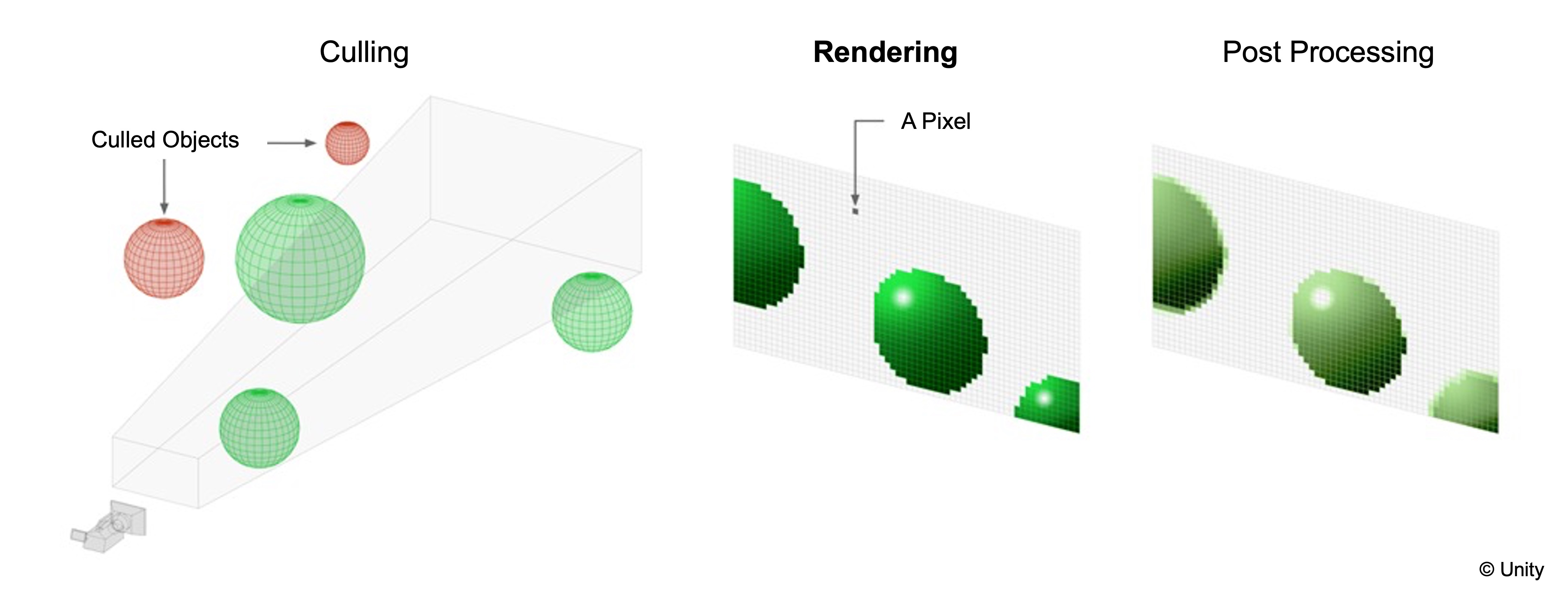
The rendering pipeline in Unity is the ordered process through which scene data is transformed into the final image displayed on screen or in an XR headset. It begins by determining which objects need to be drawn, processes those objects with materials, shaders, and lighting to generate pixel data, and finally enhances the image with post-processing effects. This pipeline ensures efficient performance while maintaining high visual fidelity.
- Culling: Culling is the first stage, where Unity decides which objects are unnecessary to render. Objects outside the camera’s view, obscured behind others (occlusion culling), or facing away can be skipped. By removing irrelevant geometry early, Unity reduces rendering workload and improves frame rates.
- Rendering: Rendering is the core stage where visible objects are drawn. Unity processes scene geometry, applies materials and shaders, evaluates lighting and shadows, and issues draw calls—commands sent by the CPU to the GPU telling it to draw specific geometry with specific rendering state. This produces the base image containing all visible elements. The rendering stage varies in detail depending on the pipeline used (Built-in, URP, or HDRP).
- Post-Processing: Post-processing is the final stage, where full-screen effects are applied to polish the image. Common effects include anti-aliasing to smooth jagged edges, bloom for glowing lights, depth of field for cinematic focus, motion blur, and color grading. These effects elevate realism and provide artistic control before the image is sent to the display or XR device. For XR, use post-processing selectively. Effects such as motion blur, depth of field, heavy bloom, and expensive full-screen effects can reduce clarity, comfort, or performance.
Imagine making a movie: Culling is like the director telling unnecessary extras to step off set so the crew only films what the audience will see; Rendering is the actual shoot, where actors perform under lights with costumes and props to capture the raw footage; and Post-Processing is the film editor polishing that footage with filters, color grading, and special effects before releasing the final cut to the audience.
Types of Rendering Pipeline
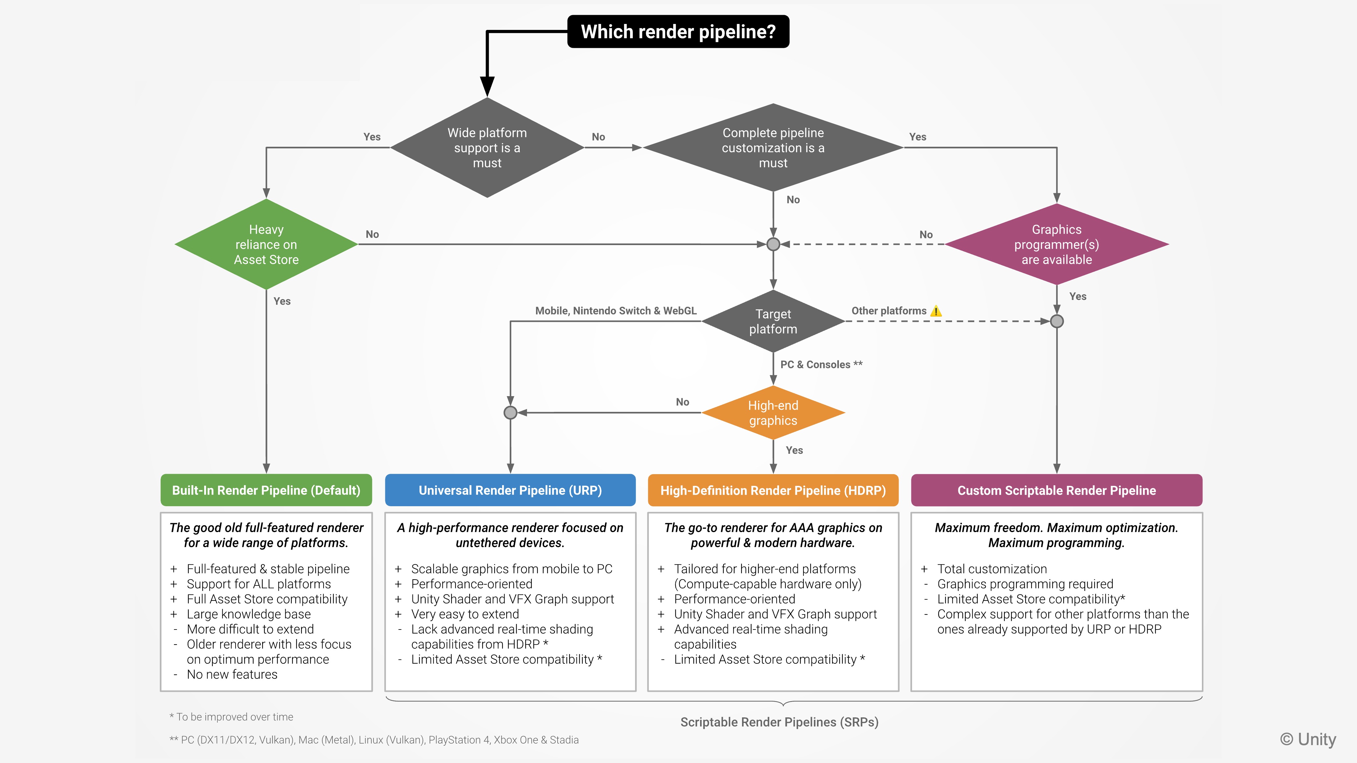
Unity provides several Rendering Pipelines. These are pre-defined sets of tools and processes that determine how rendering is performed. Each pipeline offers different trade-offs in performance, flexibility, and visual fidelity. For engineering simulations like XFactory, choosing the right pipeline is critical based on target devices and the required level of realism. Unity’s modern pipelines are part of the Scriptable Render Pipeline (SRP) system, which allows developers to configure and extend how rendering works. To select an SRP pipeline such as URP or HDRP, assign a Render Pipeline Asset in Edit > Project Settings > Graphics. Also check Edit > Project Settings > Quality, because Quality settings can override the default render pipeline asset for specific quality levels.
- Built-in Render Pipeline: Unity’s older general-purpose rendering system. It is still useful for legacy projects and some simple prototypes, but it is not the recommended pipeline for this course’s modern URP-based XR workflow.
- Universal Render Pipeline (URP): Unity’s scalable Scriptable Render Pipeline for projects that need good performance across many platforms, including desktop, mobile, mobile AR, and untethered VR. URP is the recommended render pipeline for this course.
- High Definition Render Pipeline (HDRP): Unity’s high-fidelity Scriptable Render Pipeline for high-end desktop, console, and visualization use cases. HDRP is appropriate for tethered, high-performance simulations, CAVE-style visualization, cinematic visualization, and high-end design review, but it is usually not appropriate for standalone XR devices such as Meta Quest.
URP is the course default because it balances visual quality and XR performance across many target devices. Note that switching between Built-in, URP, and HDRP is not seamless. Materials, shaders, lighting, and post-processing settings often require conversion or recreation, so choose the render pipeline early and avoid switching mid-project unless there is a strong reason. Review this Unity documentation to learn more about URP. This Unity documentation provides detailed guidelines about choosing the right Unity render pipeline for your project.
Rendering Paths
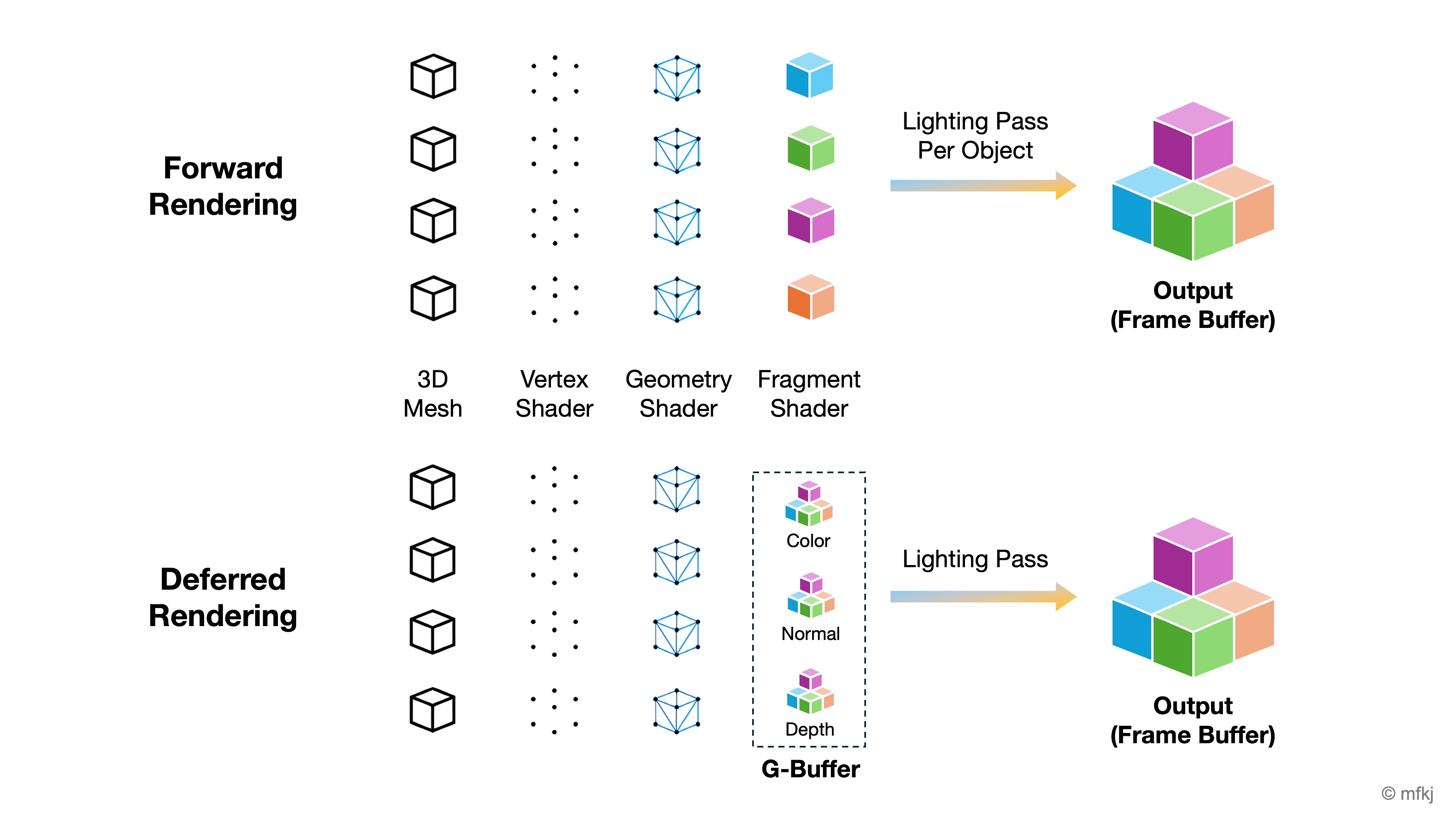
Rendering paths determine how lighting and materials are calculated for objects in the scene. The choice directly impacts performance, visual fidelity, and hardware compatibility.
- Forward Rendering: In forward rendering, Unity shades objects as they are drawn, evaluating the relevant lights for each object. It is straightforward, works well with MSAA, and is often a good choice for XR and scenes with a modest number of lights. However, many overlapping real-time lights can increase cost. Forward+ improves scalability by using tiled/clustered light lists so many lights can be handled more efficiently, depending on target hardware and URP settings. For XR, start with Forward or Forward+ unless you have a specific reason to use Deferred. Forward paths are often simpler and work well with MSAA, which is important for reducing jagged edges in headsets. Deferred can be useful for light-heavy desktop scenes but should be tested carefully on the target XR device.
- Deferred Rendering: Deferred rendering first writes visible surface data into a G-buffer—such as normals, material properties, and other per-pixel information—then applies lighting in later passes. This can be efficient for scenes with many real-time lights affecting opaque objects. The trade-offs include higher memory bandwidth, more complex transparency handling, and weaker MSAA compatibility compared with forward rendering. Deferred+ extends deferred rendering with Forward+ behavior for passes that still require forward rendering, such as transparent objects. For XR, anti-aliasing is especially important because jagged edges are more noticeable in headsets. MSAA is commonly preferred in forward-rendered XR projects, while deferred rendering may require different anti-aliasing strategies.
Imagine you’re rendering a bunch of cubes in Unity: Forward Rendering → Each cube is drawn one at a time, and for every light that hits it, Unity runs another pass to calculate shading. A few lights? Smooth. Ten lights? Each cube is redrawn many times, which gets expensive. Deferred Rendering → All the cubes are drawn once into the G-buffer, storing each cube’s position, normal, and material info. Then Unity applies all the lights afterward in a single lighting pass—much faster when lots of lights are shining on the cubes.
Adjusting Rendering Paths
In Unity using URP, rendering methods like Forward and Deferred are configured through URP assets, as follows.
- Go to
Edit > Project Settings > Graphicsand confirm the project is using a URP Render Pipeline Asset. - Also check
Edit > Project Settings > Qualityto see whether the active quality level overrides the render pipeline asset. -
In the
Projectwindow, locate the URP Renderer asset assigned by the URP Pipeline Asset. It may be named something likeUniversalRenderer,PC_Renderer, orForwardRenderer, depending on the project.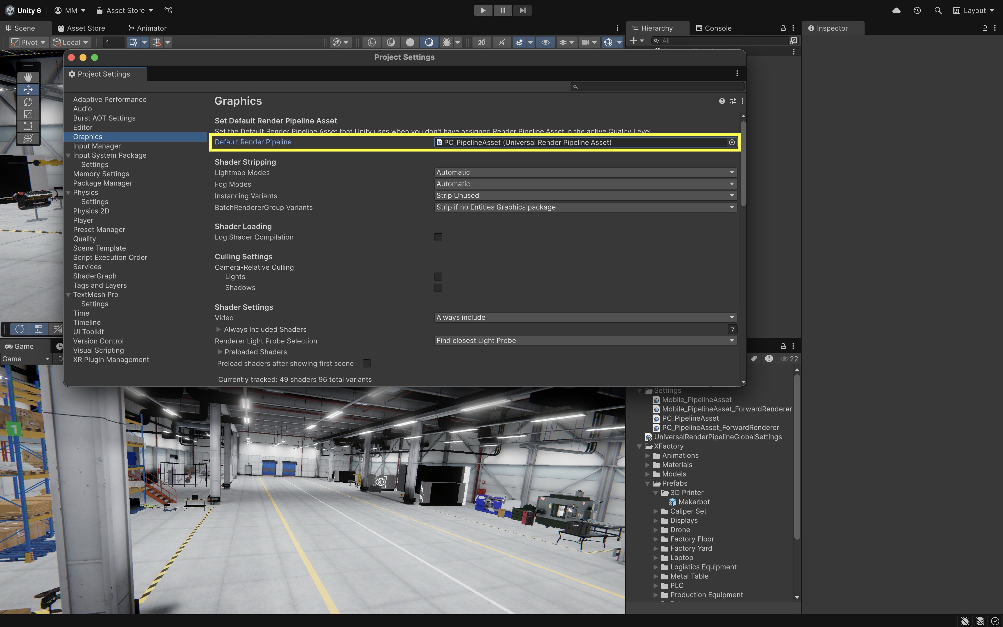
-
Select the Renderer asset and, in the Inspector, set the
Rendering PathtoForward,Forward+,Deferred, orDeferred+if those options are supported by the project configuration and target platform.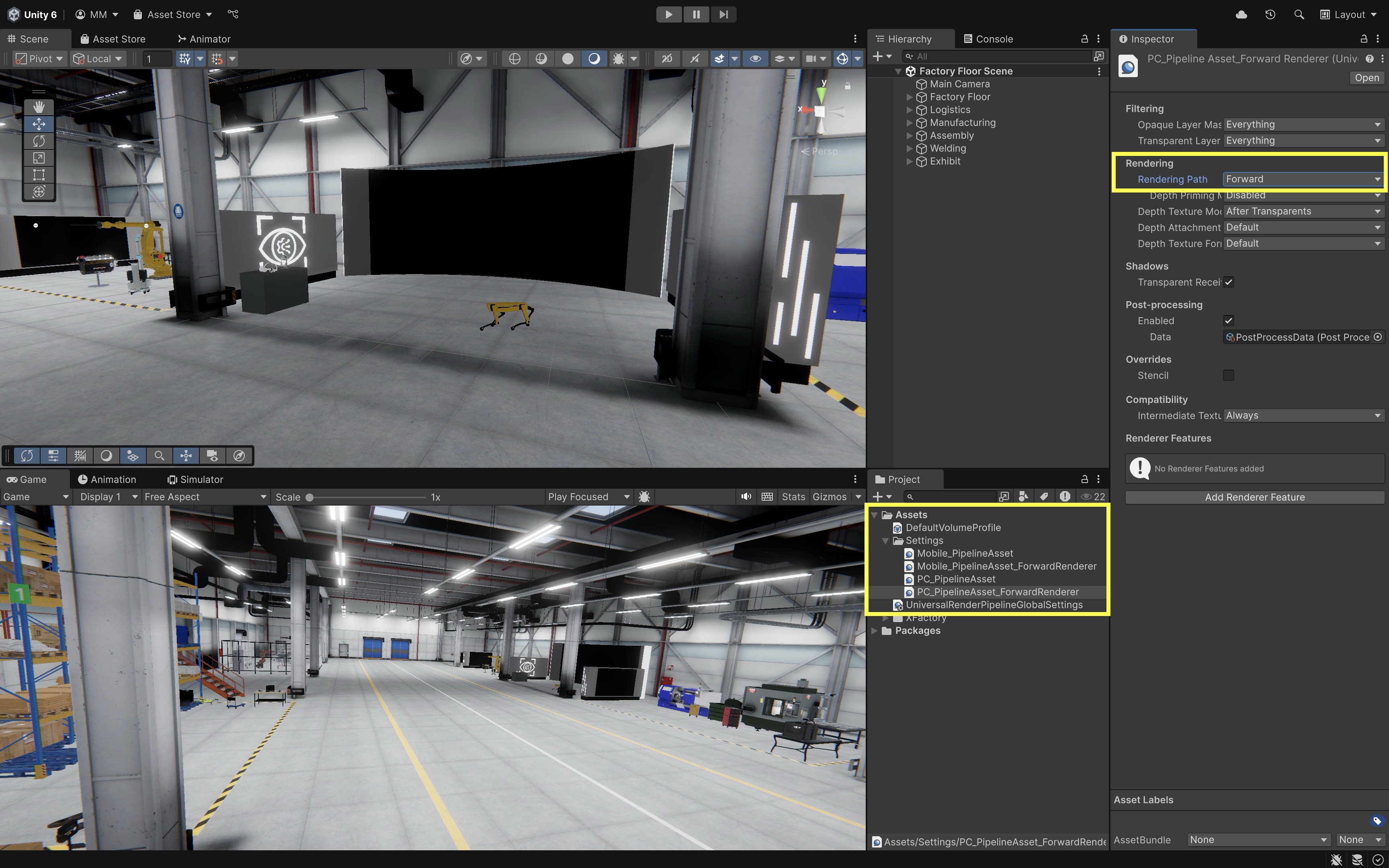
In practice, rendering path choice affects lighting cost, anti-aliasing, transparency, memory use, and XR performance. Forward is simple and often XR-friendly. Forward+ scales better with many lights while keeping many forward-rendering advantages. Deferred can help with many opaque objects and many lights, but it uses more memory and handles transparency differently. Deferred+ combines deferred rendering with Forward+ behavior for passes that still need forward rendering. Always test on the actual target device.
Key Takeaways
- Rendering converts meshes, materials, shaders, textures, lighting, and cameras into the images users see on screen.
- URP is the practical default for cross-platform XR; know how it differs from Built-in and HDRP for your targets.
- Forward vs deferred rendering paths trade lighting complexity against performance on mobile and standalone hardware.
- Mesh, material, texture, and lighting choices directly affect both realism and frame rate in XFactory-scale scenes.
- Baked lighting, light probes, and reflection probes help mix static realism with dynamic object behavior efficiently.